Ethernet Layer 2 Port Type
Interface-based VLAN division depends on the following switch port types:
Access port
An access port is used to connect to a user terminal (such as a user PC or server) that cannot identify a tag or distinguish VLAN members.
The NICs of these devices connected to the Access port tend to send and receive only untagged frames.
An Access port can be added to only one VLAN.
Trunk port
A trunk port allows data frames of multiple VLANs to pass through. These data frames are differentiated by 802.1Q tags.
A trunk port is used to connect devices such as switches, routers, firewalls, and APs.
Hybrid port
A hybrid port can be used to connect user terminals (such as user hosts and servers) that cannot identify tags, switches, routers, voice terminals, and APs that can send and receive tagged and untagged frames at the same time.
Users can specify whether a hybrid port carries a tag when sending data frames of a certain VLAN or some VLANs. The default port type of Huawei devices is hybrid, and only Huawei switches have the hybrid port.
Introduction of Access Port
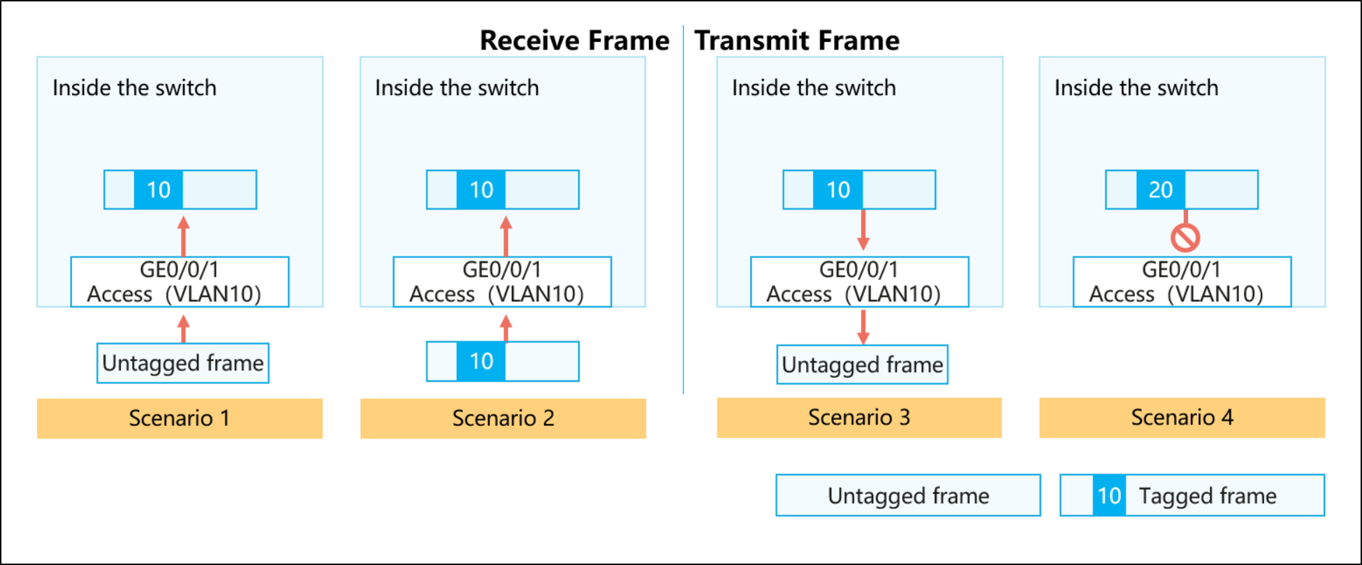
As shown in the preceding figure, four scenarios are described.
The switch adds a PVID tag to the frame and forwards the tagged frame(flooding, forwarding, discarding).
The switch checks whether the VID in the tag of the frame is the same as the PVID.
If they are the same, the Tagged frame is received or forwarded.
If they are different, the Tagged frame is discarded.
First, strip the label of the frame, and then send it out of that interface.
Disables sending the frame out of the interface.
Features of the access port
Only the data frames with the same VLAN ID as the port PVID are allowed to pass.
Introduction of the Trunk port
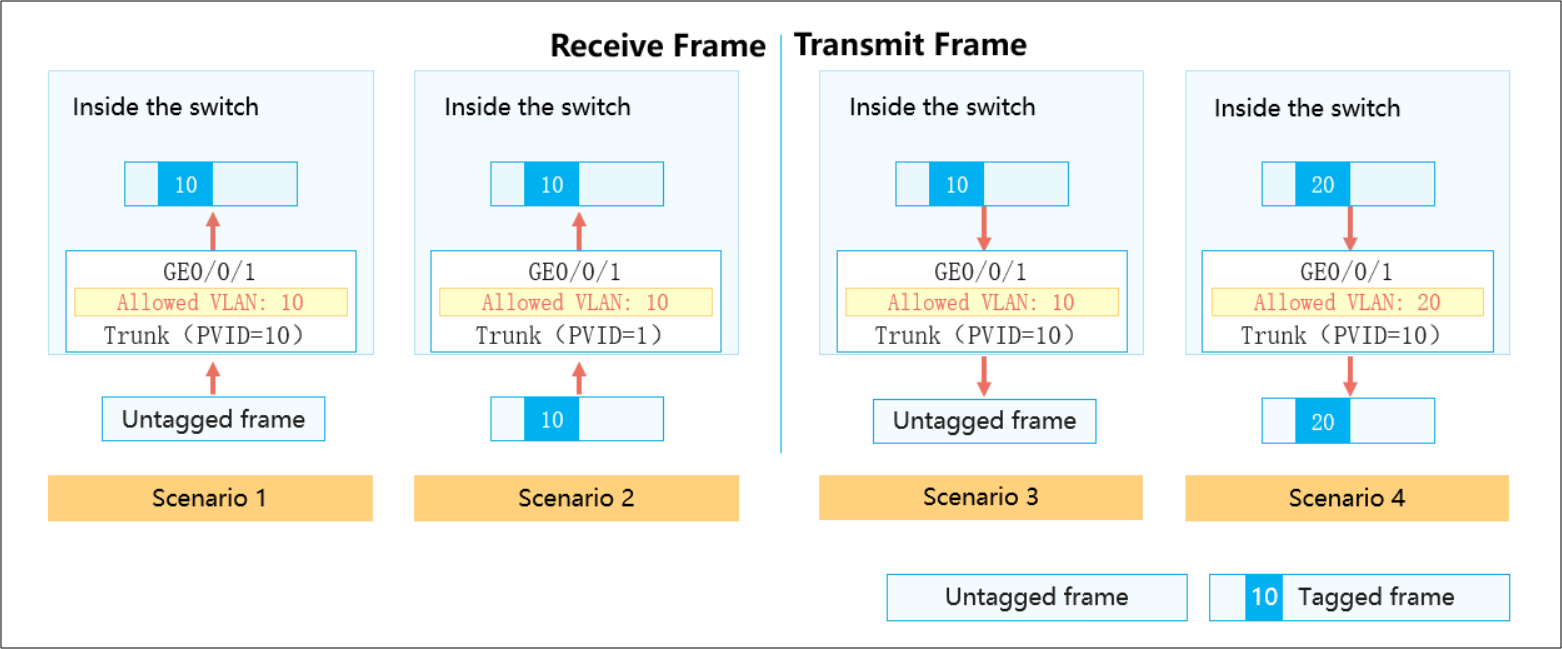
As shown in the preceding figure, four scenarios are described.
The switch adds the PVID to the frame and checks whether the PVID is in the list of allowed VLAN IDs.
If yes, the Tagged frame is received or forwarded.
If not, the label frame is directly discarded.
The switch checks whether the VID in the tag of the frame is in the list of allowed VLAN IDs.
If yes, the Tagged frame is received or forwarded.
If not, the Tagged frame is discarded.
When a tagged frame arrives at a trunk port from another port on the switch, if the VID in the tag of the frame is in the list of allowed VLAN IDs, the system compares whether the VID in the tag is the same as the PVID of the port.
If they are the same, the switch removes the tag of the tagged frame and sends the untagged frame out of the link.
Note: If the VLAN ID is not in the list of allowed VLANs, the frame cannot be sent from the interface.
When a tagged frame arrives at a trunk port from another port on the switch, if the VID in the tag of the frame is in the list of allowed VLAN IDs, the system compares whether the VID in the tag is the same as the PVID of the port.
If they are different, the switch does not strip the tag of the tagged frame but sends it directly off the link.
Note: If the VLAN ID is not in the list of allowed VLANs, the frame cannot be sent from the interface.
For the trunk port, you must configure a list of allowed VLAN IDs in addition to PVIDs. VLAN 1 exists by default.
Working Procedure of a Layer 2 Switch with VLAN and Trunk Functions
When a switch interface receives a data frame:
Construct a MAC address table by learning source MAC addresses.
Add PVID (Tag)
Forwarding Data Frames Based on the Destination MAC Address (VLAN Range)
MAC address table changes:
1) If the data frame is broadcast or multicast, the switch floods the data frame.
2) For unicast data frames, the switch queries the MAC address table and forwards the frames.
Forwards data frames through the outbound interface.
1) Remove PVID (tag).
2) Keep label forwarding. - Trunk port
Introduction of Hybrid port
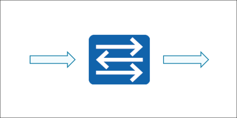
As shown in the preceding figure, four scenarios are described.
The switch adds a PVID tag to the frame and checks whether the PVID is in the untagged or tagged VLAN ID list.
If yes, the Tagged frame is received or forwarded.
If not, the Tagged frame is discarded.
The switch checks to see if the VID in the tag of this frame is in the list of untagged or tagged VLAN IDs.
If yes, the Tagged frame is received or forwarded.
If not, the Tagged frame is discarded.
Summarize scenario 3 and scenario 4. The hybrid port transmits data frames:
When a tagged frame arrives at a hybrid port from another interface on the switch, if the VID in the tag of the frame is neither in the untagged VLAN ID list nor in the tagged VLAN ID list, the tagged frame is discarded.
When a tagged frame arrives at a hybrid port from another interface on the switch, if the VID in the tag of the frame is in the untagged VLAN ID list, the switch removes the tag from the tagged frame. Then, the untagged frame is sent out over the link.
When a tagged frame arrives at a hybrid port from another interface on the switch, if the VID in the tag of the frame is in the tagged VLAN ID list, the switch does not remove the tag from the tagged frame but directly sends the tagged frame over the link.
For a hybrid port, you need to configure the PVID and two VLAN ID lists that allow packets to pass through. One is the untagged VLAN ID list and the other is the tagged VLAN ID list. By default, VLAN 1 is in the untagged VLAN list. The frames of all VLANs in the two allowed lists are allowed to pass through the hybrid port.
Features of the Hybrid port
A hybrid port allows only the data frames whose VLAN IDs are in the allowed list to pass through.
A hybrid port can allow tagged frames from multiple VLANs to pass through, and allow frames from certain VLANs to be tagged and frames from certain VLANs to be untagged.
The main difference between a Hybrid port and a Trunk port is that the Hybrid port supports data frames of multiple VLANs without tags.
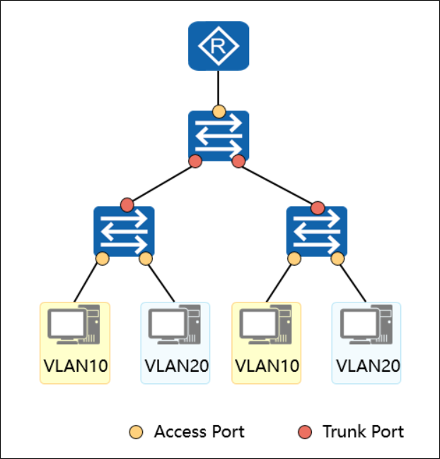
Configuration of different port types
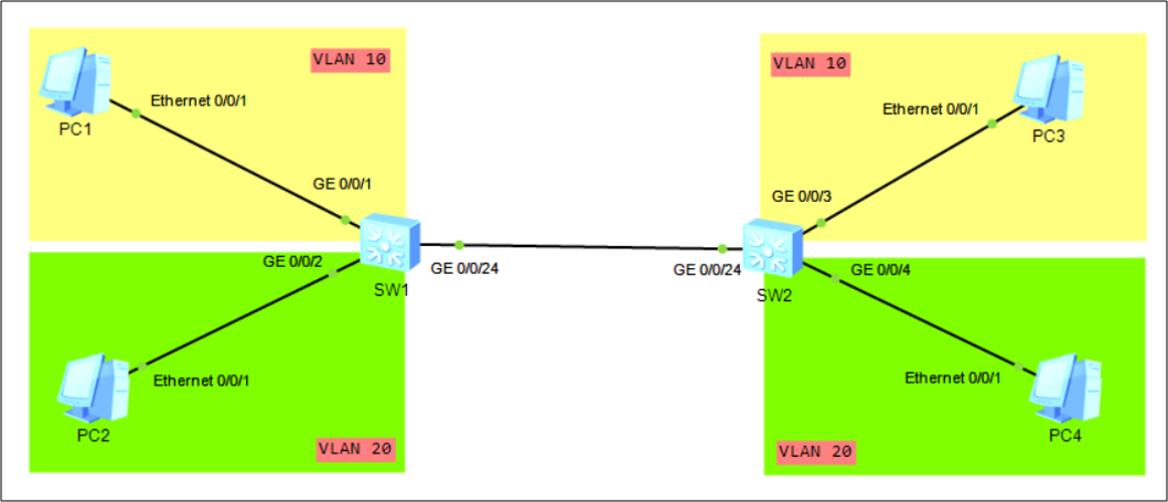
As shown in the preceding figure: Both G0/0/1 and G0/0/2 of SW1 are connected to PCs. Therefore, G0/0/1 and G0/0/2 of SW1 are configured as access ports, and G0/0/24 of SW1 is connected to SW2, and this link needs to carry two different VLANs. Therefore, G0/0/24 of SW1 is configured as a trunk port.
The configuration of SW1 is as follows:
Configuring an Access Port
[SW1] VLAN batch 10 20 --- Creating VLANs in Batches
[SW1] interface GigabitEthernet 0/0/1 --- Enter the interface view.
[SW1-GigabitEthernet0/0/1] port link-type access --- Set the link type of the interface to Access.
[SW1-GigabitEthernet0/0/1] port default VLAN 10 --- Configure the default VLAN for the interface and add the interface to the VLAN.
[SW1] interface GigabitEthernet 0/0/2
[SW1-GigabitEthernet0/0/2] port link-type access
[SW1-GigabitEthernet0/0/2] port default VLAN 20
[SW1] interface GigabitEthernet 0/0/24
[SW1-GigabitEthernet0/0/24] port link-type trunk--- Set the link type of the interface to Trunk.
[SW1-GigabitEthernet0/0/24] port trunk pvid vlan 1--- Configuring the Default VLAN for a Trunk Interface
[SW1-GigabitEthernet0/0/24] port trunk allow-pass vlan 10 20--- Adding a Trunk Interface to a VLAN
Configuring a Hybrid Port
Now let's think about whether it is possible to replace access and trunk ports with hybrid ports, and how?
Replacing Access Port Configurations with Hybrid Ports
[SW1] interface GigabitEthernet 0/0/1
[SW1-GigabitEthernet0/0/1] Port link-type hybrid --- Set the link type of the interface to hybrid.
[SW1-GigabitEthernet0/0/1] Port hybrid pvid vian 10 --- Configuring the Default VLAN for a Hybrid Interface
[SW1-GigabitEthernet0/0/1] Port untagged vian 10 --- Configure the VLANs to which the hybrid interface is added and the frames from the VLANs pass through the interface in untagged mode.
Replacing Trunk Port Configurations with Hybrid Ports
[SW1] interface GigabitEthernet 0/0/24
[SW1-GigabitEthernet0/0/24] Port link-type hybrid
[SW1-GigabitEthernet0/0/24] Port hybrid pvid vian 10
[SW1-GigabitEthernet0/0/24] Port hybrid untagged vlan 10
[SW1-GigabitEthernet0/0/24] Port hybrid tagged vlan 20 --- Configure the VLANs to which the hybrid interface is added and the frames from these VLANs pass through the interface in tagged mode.