
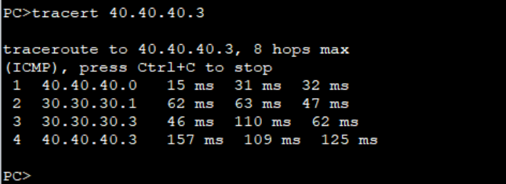
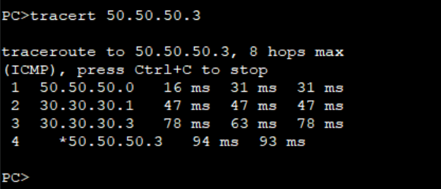
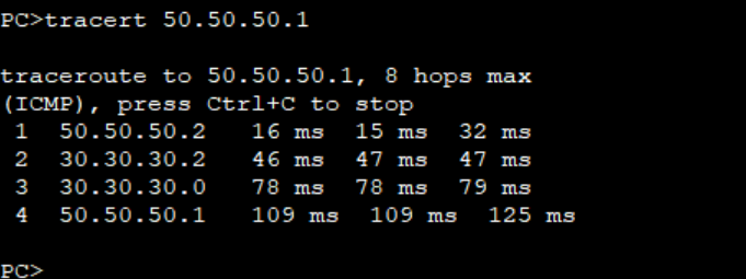
Step 1: As we verified the connectivity between PCs and the path taken by the traffic from PC2 to PC4 and PC3 to PC5.
The objective of this lab is to use Policy based routing to ensure traffic from PC2 to PC4 passes through R4 while traffic from PC3 to PC5 passes through R5.
Step 2: Configure ACLs to match traffic from PC2 and PC3 as follows on R3. We use extended ACLs to be able to match the source IP addresses.
***************************R3
#
acl number 3000
 rule 5 permit ip source 40.40.40.0 0.0.0.1
#
acl number 3002
 rule 5 permit ip source 50.50.50.0 0.0.0.1
#
Step 3: Configure PBR and apply it on the interfaces facing PCs on R3.
**************************R3
#
policy-based-route TEST_PBR permit node 5
if-match acl 3000
apply output-interface Serial0/0/0
policy-based-route TEST_PBR permit node 10
if-match acl 3002
apply output-interface Serial0/0/1
#
interface Ethernet0/0/0
ip policy-based-route TEST_PBR
#
interface Ethernet0/0/1
ip policy-based-route TEST_PBR
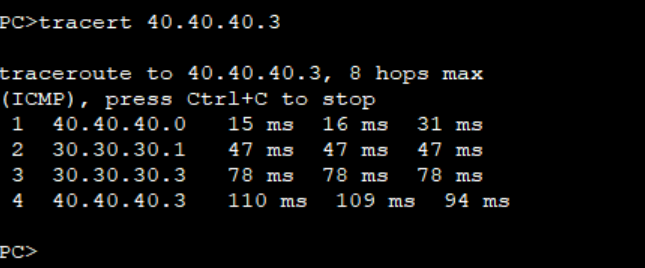
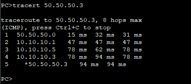
#Step 4: Verify the path taken by traffic from PC2 and PC3.
Note: The PBR configured on R3 doe not affect the path for the return traffic from PC4 and PC5. You must configure same PBR on R6 to be able to control the flow of the return traffic.
This is how you can use PBR to control traffic flow in your network. Thank You for reading and please leave your comments below. Check out other related articles on our page.
No comments:
Post a Comment