Friday, 23 June 2017

MIKROTIK:-2 ISP link load balancing through default route

This is very much important to know the load balancing method between 2 isp's .


please follow the below steps and make it configure in proper order . There are many ways to configure the Load balancing between 2 wan link...But here i am going to show a simple way to make it configure .


Let's start the configurations for load balancing .

Step-1
Configure The IP address .


/ip address
add address=172.20.20.1/30 comment=VODA interface=eth1 network=172.20.20.0
add address=172.20.20.5/30 comment=AIRTEL interface=eth2 network=172.20.20.4
add address=172.21.21.1/24 comment=MY_LAN interface=eth3 network=172.21.21.0


Step-2

Configure the mangle

Create the Mark  Connection for IN and Create Mark routing For OUT

/ip firewall mangle
add action=mark-connection chain=input in-interface=eth1 \ new-connection-mark=VODA_IN
add action=mark-connection chain=input in-interface=eth2 \ new-connection-mark=AIRTEL_IN
add action=mark-routing chain=output connection-mark=VODA_IN \ new-routing-mark=VODA_OUT
add action=mark-routing chain=output connection-mark=AIRTEL_IN \ new-routing-mark=AIRTEL_OUT


Step-3

Configure The NAT for both the interface.

/ip firewall nat
add action=masquerade chain=srcnat out-interface=eth1
add action=masquerade chain=srcnat out-interface=eth2

Step-4

Configure the Default Route for both the gateway with different diffrenet Distance
number and along with that you have to select the routing mark also .


/ip route
add check-gateway=ping distance=1 gateway=172.20.20.2 routing-mark=VODA_OUT
add check-gateway=ping distance=2 gateway=172.20.20.6 routing-mark=AIRTEL_OUT
add check-gateway=ping distance=1 gateway=172.20.20.2,172.20.20.6

MikroTik:How to find Mail spammer in your network

Sometimes you may see when you are torching the interface in that case it's showing huge SMTP traffic so if there is any false connection has been established over SMTP protocol then you can find these hosts in your network ..


/ip firewall filter
add action=add-src-to-address-list address-list=spammer address-list-timeout=\
    1d chain=forward comment="spam 25 port listing rules" connection-limit=\
    60,32 dst-port=25 protocol=tcp
add action=drop chain=forward comment="spammer's mail deny" dst-port=25 \
    protocol=tcp src-address-list=spammer

Or

/ip firewall filter
add action=add-src-to-address-list address-list=spammer address-list-timeout=\
    1d chain=forward comment="25 port listing rules" connection-limit=60,32 \
    dst-port=25 limit=60,5 protocol=tcp
add action=drop chain=forward comment="spammer's mail" dst-port=25 protocol=\
    tcp src-address-list=spammer

MIKROTIK:-How To give high bandwidth to your video streaming traffic .

This is one of the most common technology in the ISP domain .


Sometimes you can see most of the customers are facing the traffic dropped issues in Video streaming .


I want to give the high priority bandwidth to all my users when they are accessing any video server 
over the internet . And as i tested if you are using the Google connection form these service provider like Mumbai CH and Extreeme and also you can choose anyone service provider but this is the rule will help you out to filter video streaming traffic in your network and easily you can set the bandwidth to your customers for video traffic only  .

And as per the my experience it also works fine for facebook videos,youtube videos   .

Here i am using this below scenario .


Lets start the configuration ..

I am not configuring the basic configuration here . because already i have posted some basic technologies about Mikroitk  .like ,IP address configuration , Default Route , NAT etc etc ...


Step-1


Goto IP>Firewall>Layer 7


You can use the below command to add the scri

/ip firewall layer7-protocol
add comment="" name=ALL_Video regexp="videoplayback|video"

Step-2


Then Crete the Mangle rule to mark the Video streaming packets .


Use the below command to create the mangle rule.

/ip firewall mangle
add action=mark-packet chain=forward layer7-protocol=ALL_Video new-packet-mark=\
    Video_Streaming passthrough=yes


Step-3

Create the Queue .

This is completely depends on you because as per your requirement you can give the bandwidth to all the customers .

You can give same bandwidth for all the users .and also you can select a specific amount of bandwidth for this video streaming users .


If you want to give the same speed to each users then you have to create the PCQ . 


Here I am  going to give extra 2mbps  more  for all my Video streaming traffic .

Create the PCQ first using this below command .


/queue type
add kind=pcq name=2mbps_UP pcq-classifier=src-address pcq-dst-address6-mask=64 \
    pcq-rate=2M pcq-src-address6-mask=64
add kind=pcq name=2mbps_DN pcq-classifier=dst-address pcq-dst-address6-mask=64 \
    pcq-rate=2M pcq-src-address6-mask=64


Create a simple queue using the packet marks  .


After configuring the above things you will be able to see the traffic against of your created queue for video streaming .


MIKROTIK:-How To filter and block The Facebook In Mikrotik Routers

This is an important chapter i am going to discuss on .


Lets get into the topic .

In this scenario I am going to block the facebook  for my LAN users and likewise you can block any of the website using layer 7 protocol but if the client is using VPN to access this website then this rule will not work successfully .


Here is the given below my scenario.


I am not configuring the basic configuration here . because already i have posted some basic technologies about Mikroitk  .like ,IP address configuration , Default Route , NAT etc etc ...


Lest get in to the IP >Firewall>Layer7


and also you can run the below command in CLI .


/ip firewall layer7-protocol
add name="Block Site" regexp="^.+(facebook|youtube).*$"


After adding this in you have create a Filter rule against this layer7 protocols..


Lets create a filter rule ..


/ip firewall filter
add action=drop chain=forward disabled=yes dst-port=80,443 layer7-protocol=\
    "Block Site" protocol=tcp src-address=192.168.0.0/24


Here I have mentioned the source IP address list but if you want to block the these contents 
in your complete network then you dont need to assign any source IP .


This is the best practice to make disable the contents and also you can filter the traffic using teh layer 7 to give the prioritise . 


Monday, 19 June 2017

Redhat- Password Protection to the users .


Redhat-User Management.

Before we create the user we must have to know the concept of Group .


What Is Group ?

A group is a collection of users and the purpose is  to create the group is to give some certain
permission to some specific users .

Find the below commands to create the users and Groups .


Note :-All those groups and related files are kept in /etc Directory .

and also you can see the etc directory

[root@laxmi rhcsa]#cd /etc
[root@laxmi etc]#ls -l group
-rw-r--r--. l root root 1026 Jun 19 20:23 group
[root@laxmi etc]#cat group 


You can see in the end there showing a digit ,This Numbers is the Group ID and this is the unique to each and every group .

Create a group 

[root@laxmi etc]#groupadd barik

To see the details about group please run the below commands .

[root@laxmi rhcsa]#cd /etc/group


How To Delete a Group ?


Lets delete this group .


[root@laxmi etc]#groupdel barik


Group should be created first before you created the users otherwise you will not able to add the user in a particular group .


User Administration 

Lets Create The users .

The below directory contains the users information . once you will run the below command s then you will be able to see the list of users in this directory .


[root@laxmi etc]#cat /etc/passwd


Lets Create The users .

[root@laxmi etc]#useradd -g laxmi -u1001 -d /home/laxmidhar -s /bin/ksh laxmidhar

-u means User Id
-d means This is the home directory of user 
-s means shell 


Lets Modify The users .


I want to change the shell of the user

[root@laxmi etc]#usermod -s /bin/bash laxmi


 Lets Delete The users now .


[root@laxmi etc]#userdel  laxmidhar


In here , I have created a user with a particular home directory so once you will run the above command then the user account will be deleted but still there is  the home directory for that user .

So for recommendation you have to run the below command for user deletion .


[root@laxmi etc]#userdel -r laxmidhar


After run the above command you can see there is no home directory for this user .


Lets verify that .


[root@laxmi etc]#cd /home(Go in to the home directory )

[root@laxmi home]#ls -lrt


How to lock The user ?

[root@laxmi home]#usermod -L laxmi

Once you will lock the user then that user will not be able to login into the system .

How to unlock lock The user ?


[root@laxmi home]#usermod -U laxmi


How to verify that user is locked or unlocked ?


[root@laxmi home]#cat /etc/shadow


If there is showing you first exclamation sign then that user is locked and if there is showing you the second exclamation then there is no any  password for the users .


To unlock this user .


[root@laxmi home]#usermod -U user1

Thursday, 15 June 2017

MIKROTIK:-Priority Based Queue

 Queue prioritises name says it self we can set the priority based on your  

Tuesday, 13 June 2017

MIKROTIK:-Mikroitk PCQ .

PCQ:-Per Connection Queue.


When should we use ?

Using this method you can set the priority for group of IP's and the marking of packets and basically it's used for to provide the rate limit to group of contents and it will work like per connection established wise.


lets you have 10.000 customer in your network and you want to restrict on each IP, In that case it would be very difficult to create the 10000 queue manually .So there is an alternative way to way
make it configure through PCQ and  there is one disadvantages is this queue will be apply same bandwidth and same priority on per host .


lets start the configure .


I have many customers I have given them a IP to use the internet and being an ISP i have to control and limit  the bandwidth to them .Lets I want to restrict to each hosts on 2mbps .


Create the PCQ First .


Queue>Queue Types.


Create 2 PCQ queue for upload and download .


please find the details below .

Pcq-1


Pcq-2


Please find command details below .

/queue type
add kind=pcq name=1Mb_UPload pcq-classifier=src-address pcq-dst-address6-mask=\
    64 pcq-rate=1M pcq-src-address6-mask=64
add kind=pcq name=1Mb_Download pcq-classifier=dst-address \
    pcq-dst-address6-mask=64 pcq-rate=1M pcq-src-address6-mask=64

Step-2

Assign this PCQ in Simple Queue .

please find the details below images and commands .


Commands .

/queue simple

add name="Customer A" queue=1Mb_UPload/1Mb_Download target=10.0.0.0/24


As you can see on my below commands and images , I have assigned a network is 10.0.0.0/24 network , It means whoever the host will be assigned the IP address from this network that host will get 2mbps .

In Target option you can select any particular interface and and you can give a complete network if you want to restrict the bandwidth on complete network like ;.(10.0.0.0/24). and also you can set to limit the traffic on particular destination .


Monday, 12 June 2017

All ISP Networking Technologies(L.D Barik): MIKROTIK:-Manually Created queue added in PRTG for...

All ISP Networking Technologies(L.D Barik): MIKROTIK:-Manually Created queue added in PRTG for...: If you want to add your manually created queue in PRTG for monitoring purpose then you have to add that queue in PRTG using OID value . ...

CENTOS:-How to give the IP address in CENT OS minimal

Cent OS Minimal: The main way of managing a linux server system is via SSH. Most linux servers are "headless", that is, without a GUI because there's no use in having a GUI when accessing a server via SSH as you'll only see the console, not the GUI.


Choosing the minimal install gives you the ability to add only the packages you want and need, instead of forcing you to remove all the packages that comes bundled with the GUI, and then install the packages you want and need.


That way it's less work for the administrator and less attack vectors for the cracker.This is a minimal version of the “bin” CentOS OS install. You would use this instead of “bin” if you do not need anything but a truly utterly bare CentOS OS install with pretty much no GUI.


This is good for server environments where you really only need Terminal access and a core OS. This is most likely what you want to use but just note: It is truly minimal and more-minimal than even an Ubuntu “server”/minimal install equivalent.


Read up here for more details on how you might need to install a few packages via yum install I would have expected would be a part of any minimal install. Apparently you can easily clear up this excessive “minimalism” issue by just running yum groupinstall base right after installing a minimal OS. So that’s an option as well.


Step-1

Login Into the system after giving the username and password .


Step-2

Run The below commands and follow the below steps  .

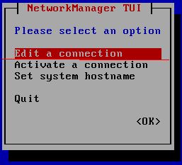
nmtui (and press the enter )

Click On Edit a Connection


Now choose you network interfaces and click Edit


Now Give the IP address .


After Giving the IP address in interface you need to restart the Network services .To  restart the network services please use the below command.


service network restart


After restarting the Network services you will be able to see the ip address is changed .To see the IP address in interface please run the below commands.


ip a  (Press the enter )

Wednesday, 7 June 2017

MIKROTIK:-Mikroitk Simple Queue .

This is one of the very well known features in the mikrotik when we talk about QOS . and you can control the rate limit of downloading and uploading traffic on each interface and IP, and also any particular marking packets ,


This features alows you to  limiting the bandwidth rate and it is is used to control the rate of traffic flow sent or received on a network interface. Traffic which rate that is less than or equal to the specified rate is sent, whereas traffic that exceeds the rate is dropped or delayed.


Lets start the configuration .


I have a customer I have given them a IP to use the internet and being an ISP i have to control and limit  the bandwidth to them .Lets I want restrict them on 2mbps .


Step-1

Queue >Simple Queue.


/queue simple
add max-limit=2M/2M name="Customer A" target=10.0.0.2/32


Name:-The Queue name you can give anything .

Target:-The target is defines to identify the souce IP or interface and In this case statement works right also if we indicate only one of parameters: "target=" or "interface=", because both of these define where and for which traffic this queue will be implemented.

In Target option you can select any particular interface and and you can give a complete network if you want to restrict the bandwidth on complete network like ;.(10.0.0.0/24). and also you can set to limit the traffic on particular destination .


Max-Limit:-It will restrict you in your exact Maximal upload/download data rate that is allowed for a target to reach to reach what


MIKROTIK:-Manually Created queue added in PRTG for monitoring .

If you want to add your manually created queue in PRTG for monitoring purpose then you have to add that queue in PRTG using OID value .


OID -Object Identifier .

OIDs are generally provided by the hardware manufacturers or can be found in so-called OID repositories, where collections of MIB trees and the corresponding OIDs can be accessed. PRTG reads these OIDs and appoints them the device they belong to. That means that it monitors a selected device and its specific OID.

Using OID you can monitor all the things of mikroitk . Like .Bandwidth Utilization,Cpu Usage,Memory usage.Etc.Etc..


Hosts receive SNMP generated messages on UDP port 161 (except the trap messages, which are received on UDP port 162).

Please fnd the details below which information I have collected from mikrotik Official website for 
better understanding .

OID stands for an object identifier, which is a data type specifying an authoritatively named object. An object identifier is a sequence of integers separated by decimal points. These integers traverse a tree structure, similar to the DNS or a Unix filesystem. There is an unnamed root at the top of the tree where the object identifiers start. All variables in the MIB start with the object identifier 1.3.6.1.2.1. Each node in the tree is also given a textual name. The names of the MIB variables are the numeric object identifiers, all of which begin with 1.3.6.1.2.1. You can use the SNMP protocol to get statistics from the router in these submenus:


To see the OID for each services .

/interface
/interface pc
/interface wavelan
/interface wireless
/interface wireless registration-table
/queue simple
/queue tree
/system identity
/system license
/system resource


Lets Start the configuration .


Step-1
Please find the OID of your quees .


[admin@ngc-01] > /queue simple print    
Flags: X - disabled, I - invalid, D - dynamic 
 0    name="PRTG" target=13.13.13.2/32 parent=none packet-marks="" priority=8/8 
      queue=default-small/default-small limit-at=0/0 max-limit=4M/4M 
      burst-limit=0/0 burst-threshold=0/0 burst-time=0s/0s bucket-size=0.1/0.1 

 1    name="LAX" target=13.13.13.3/32 parent=none packet-marks="" priority=8/8 
      queue=default-small/default-small limit-at=0/0 max-limit=4M/4M 
      burst-limit=0/0 burst-threshold=0/0 burst-time=0s/0s bucket-size=0.1/0.1 


Here , In my scenario I have created 2 queue in SNMP for monitoring .

[admin@ngc-01] > /queue simple print oid
Flags: X - disabled, I - invalid, D - dynamic 
 0    name=.1.3.6.1.4.1.14988.1.1.2.1.1.2.64 
      bytes-in=.1.3.6.1.4.1.14988.1.1.2.1.1.8.64 
      bytes-out=.1.3.6.1.4.1.14988.1.1.2.1.1.9.64 
      packets-in=.1.3.6.1.4.1.14988.1.1.2.1.1.10.64 
      packets-out=.1.3.6.1.4.1.14988.1.1.2.1.1.11.64 
      queues-in=.1.3.6.1.4.1.14988.1.1.2.1.1.12.64 
      queues-out=.1.3.6.1.4.1.14988.1.1.2.1.1.13.64 

 1    name=.1.3.6.1.4.1.14988.1.1.2.1.1.2.65 
      bytes-in=.1.3.6.1.4.1.14988.1.1.2.1.1.8.65 
      bytes-out=.1.3.6.1.4.1.14988.1.1.2.1.1.9.65 
      packets-in=.1.3.6.1.4.1.14988.1.1.2.1.1.10.65 
      packets-out=.1.3.6.1.4.1.14988.1.1.2.1.1.11.65 
      queues-in=.1.3.6.1.4.1.14988.1.1.2.1.1.12.65 
      queues-out=.1.3.6.1.4.1.14988.1.1.2.1.1.13.65 


Step-2

Go To the PRTG system and create the below things .

1-Before you add a sensor you have to add that mikroitk  into your PRTG server .


Command to configure the SNMP in Mikrotik .


/snmp
set contact="Mikroitk NAS" enabled=yes location=NOC_Room trap-generators=\
    interfaces trap-target=13.13.13.2


Step-3.

After Snmp Configuration in mIkoritk then you have to add that device in PRTG Server .

Go To>Local Probe>Add Device .


Now you will be able to ADD the  Censer.

Right Click On the Device and Add the censors .Please find the  below details for complete configuration .


You Have to use this OID which is shown in below picture .And Also on above I have mentioned the OID of my queues ,


Once you will be completed the above steps the censer will be added in your PRTG censers list under this mikroitk Device.and It will  detect automatically to the mikrotik queues which you have added .


Now you can check the censer and you can check the  usage bandwidth as well .


Tuesday, 6 June 2017

MIKROTIK:-Queue(QOS) All about in Mikroitk

Queues are used to limit and prioritise the  traffic based on your requirement and there is lots
 of mechanism to configure the QOS in Mikrotik OS:


Why Do we need QOS ?


We can limit data rate for certain IP addresses, subnets, protocols, ports, and other parameters.

limit peer-to-peer traffic.
prioritise some packet flows over others.
configure traffic bursts for faster web browsing.
apply different limits based on time.
share available traffic among users equally, or depending on the load of the channel.


Queue Types in mikroitk .

1-FIFO-First In and first Out.
2-RED-Random Early Drop
3-SFQ-Stochastic Fairness Queuing
4-PCQ-Mostly this queening mechanism is being used in every-times .The queuing configuration is depends on your
requirement and one more thing this queue will be applied on per connection .It means which ever the bandwidth
you have mentioned inside the queue that same parameter will be applied on all the established connections .
 For example if you classify flows by src-address on local interface (interface with your clients), each PCQ sub-stream will be one particular client's upload.
It is possible to assign speed limitation to sub-streams with pcq-rate option. If pcq-rate=0 sub-streams will divide available traffic equally.


Simple Queue .

This is one of the way to limit data rate for specific IP addresses and/or subnets,

Some Key points on Simple Queues .

Peer-to-peer traffic queuing
You can set the priority of each queues.

Note-

The queues will be working in ascending order so I mean to say that you have to make it proper alignment before you expect the impact of the queues .


MIKROTIK:-HOTSPOT user login without Radius .

If you dont have any radius server in your network and you want to create the users in Mikrotik NAS in that case , The mikrotik will  verify the users name and password  and after that they will be able to login So first of all you have to create the users in Mikrotik router and like wise you can assign the bandwidth  for the users individually  .


Before you create the user in mikrotik router you have to have a IP pool in yopur mikrotik . Because the users will get the IP address from that Pool only and also you have to add the IP in the mikroitk  interface  .

Step-1

Configure the IP address in interface .


/ip address

add address=100.0.0.1/24 interface=ether6 network=100.0.0.0


Step-2

/ip pool
add name=HOtspot ranges=100.0.0.2-100.0.0.254


Step-3

Go To IP>HOTSPOT> USER>And Add(+)


/ip hotspot user

add address=100.0.2.2 name=laxmi password=12345 server=hotspot1


After configure the user you will be able to login using this username and password and given IP address you have use .


If you want to give same bandwidth for each users then you have to create a different profiles for each users  .


/ip hotspot user profile
add !idle-timeout name=laxmi rate-limit=512k/1M shared-users=unlimited


MIKROTIK:-Hotspot firewall rules for DNS Attack. .

You may see in live scenario your mikrotik is getting huge DNS request from internet and so the users are getting the DNS resolve problem and also it can create a big impact on your netwwork .

Please add these below firewall rules when you are seeing huge DNS request from internet.


/ip firewall filter
add action=drop chain=input dst-port=53 in-interface=ether1 protocol=udp
add action=drop chain=input dst-port=53 in-interface=ether1 protocol=tcp

In here eth1 is my WAN interface which is connected to ISP .and eth 6 is my LAN Interface.

This above firewall rule will help you to reduce the DNS request from WAN but some times it can create some problem for LAN users so you have to add this below  rule for LAN interface.

/ip firewall filter
add action=drop chain=forward dst-port=53 out-interface=!ether6 protocol=udp
add action=drop chain=forward dst-port=53 out-interface=!ether6 protocol=tcp


MIKROTIK:-Hotspot DNS Bypass

According to my experience and as I have seen sometimes in mikrotik router the mikroitk is blocking the DNS IP address and DNS Port itself when we are running the hotspot in our mikroitk .

So if you are facing this problem in your in live scenario then you can go for this solution if hotspot is blocking the DNS IP and DNS Port .

Lets Bypass all the DNS IP

Go To IP>Hotspot>IP Binding 


/ip hotspot walled-garden ip

add action=accept disabled=no !dst-address dst-port=53 protocol=udp \
    !src-address
add action=accept disabled=no !dst-address dst-port=53 protocol=tcp \
    !src-address

/ip hotspot ip-binding

add address=8.8.8.8 type=bypassed
add address=4.2.2.2 type=bypassed

MIKROTIK:-Hotspot Bypass For specific Destination IP with specific source IP. .

As I discussed in my previous topic , if you are entering any source network pool or any source IP in the walled garden IP lists for accessing some particular destination IP without any login  , That means those users from that IP pool are going to access that destination server  without any login .


Let's Here I have one IP pool and I am going to make proxy for that entire network with some particular one destination server IP  and also you can make proxy for one single user with any destination server but based on your requirement you can configure .


Lets in my case I am going to make proxy for one ip which is 100.0.1.2 and this IP of any user will be able to get the access of Google.com without any login  and another proxy for one complete network(100.0.3.0/24) to access the facebook.com without any login  .


Lets begin the configuration .

The IP address is given below of my both the servers ,

> google.com

          172.217.26.206


> facebook.com

Name:    facebook.com
Addresses:  2a03:2880:f126:83:face:b00c:0:25de

          31.13.78.35


Please find the commands below for references.

/ip hotspot walled-garden
add comment="place hotspot rules here" disabled=yes

/ip hotspot walled-garden ip
add action=accept disabled=no dst-address=172.217.26.206 !dst-port !protocol \
    src-address=100.0.1.2
add action=accept disabled=no dst-address=31.13.78.35 !dst-port !protocol \
    src-address=100.0.3.0/24 

MIKROTIK:-Hotspot Bypass For specific Destination IP in walled Garden IP List .

As I discussed in my previous topic , if you are entering any destination network pool or destination  IP in the walled garden IP lists , It means all the users will be able to access this destination address without any login .


This most used in ISP network for expired users . For example lets you have one official website and you have integrated the Payment gateway so your expire users can pay via online and after that they can make activate their user account . 

So the user has to be reachable to your payment gateway site with out any internet so the users can pay over there .  To provide this reach-ability from users computer to your payment gateway you have to bypass the destination IP address of your payment gateway website so you user can access your your payment gateway website without any login .


Please find the details below configuration .


Please find the details below command .


/ip hotspot walled-garden
add comment="place hotspot rules here" disabled=yes

/ip hotspot walled-garden ip
add action=accept disabled=no dst-address=11.11.11.199 !dst-port !protocol \

    !src-address

MIKROTIK:-Hotspot Bypass For specific Source IP in walled Garden IP List .

As I discussed in my previous topic , if you are entering any source network pool or source IP in the walled garden IP lists , That means those users from that IP pool are going to use the internet without any login .


Let's Here I have one IP pool and I am going to make proxy for that entire network and also you can
make proxy for one single user but based on your requirement you can configure .


Lets in my case I am going to make proxy for one ip which is 100.0.1.2 and another proxy for
one complete network(100.0.3.0/24) .


Lets begin the configuration .


The configuration is very simple and please find the command's below .


/ip hotspot walled-garden
add comment="place hotspot rules here" disabled=yes

/ip hotspot walled-garden ip
add action=accept disabled=no !dst-address !dst-port !protocol src-address=\
    100.0.1.2
add action=accept disabled=no !dst-address !dst-port !protocol src-address=\
    100.0.3.0/24


MIKROTIK:-Hotspot PROXY .

Hotspot proxy means to bypass all the users in mikrotik , It means all the users will get the internet without any login so this feature will allows you to bypass the users and they will use the internet without with unlimited speed of bandwidth until you have not configured any queue for them manually..


And also you can you bypass some specific user against their IP so they can use the internet without any login .


The configuration is very simple so please find the details below .


Please find the details Below commands to configure .


/ip hotspot walled-garden
add comment="place hotspot rules here" disabled=yes
/ip hotspot walled-garden ip
add action=accept disabled=no !dst-address !dst-port !protocol server=hotspot1 \
    !src-address

MIKROTIK:-IP Bypass In HOTSPOT.

In this topic we will discuss the bypass on Mikrotik Hotspot Login. Bypass means access to hotspots no longer need to enter a username andpassword to login hotspot. Be sure to enter the RouterOS Mikrotik through WinBox. Once able to get into RouterOS Mikrotik, select the IP >> Hotspot.

On the screen there are a lot of menu hotspots. To bypass the hotspot login, we can use the IP Bindings, Walled Garden or can also use IP-Walled Garden.

you can bypass the IP address agianst on one particular MAC address and the important thing is
you are bypassing any particular networks and any paarticular IP address in that case the users
dont have to login using the user name and password .


Please Find the details below .

Go To IP>Hotspot>IP Binding 


Please find the below command to make it configure .,


/ip hotspot ip-binding
add address=100.0.1.0/24
add address=100.0.2.0/24
add address=100.0.3.0/24
add address=100.0.4.0/24
add address=100.0.2.2 to-address=100.0.2.2 type=bypassed
add address=0.0.0.0/0 type=blocked

Monday, 5 June 2017

MIKROTIK:-IP Binding In HOTSPOT.

This is one of the features in hotspot which is very important to know that , As you are working in ISP and you are having a big customer-base in that case once all of your will be connected to the hotspot interface in that case you can see some of the IP list in your HOTSPOT's host lists which is not your LAN ip .SO  you have to block all the IP address except your LAN IP .


Here in my case I am using 4 IP pools which is given below .

100.0.1.1/24
100.0.2.1/24
100.0.3.1/24
100.0.4.1/24

But I am going to see in hotspots host list it's showing me some IP pools which is not being used in my network. So i have to block all the IP except my LAN ip .


As you can see in my below picture , I have allowed all my network and in the end i have blocked all the IP which means (0.0.0.0/0). This rules means all the IP's will be blocked except my 4 ip pool ,


NOTE;-The blocking rules should be in last .Because if there is permitted rule which is existed after the denying rule in that case the permitted rule will not work .So the block or deny rules should be in the last . Because the rules are checking in ascending order(0--1--2--3--3---4...100).


Please find the commands below .


/ip hotspot ip-binding
add address=100.0.1.0/24
add address=100.0.2.0/24
add address=100.0.3.0/24
add address=100.0.4.0/24
add address=0.0.0.0/0 type=blocked


MIKROTIK:-Types Of Login in HOTSPOT

The HOTSPOT services provide us the different type of authentication mechanism to access the services , It means there are lots of customisation you can do based on your requirement .

1-HTTP Login .


HTTP login is the process which allows to the user to open up the login page in the browser and will have to login with giving the username and password which you have created in your RADIUS.

Lets you don't have any radius server in your network and you are using the mikrotik it self as NAS
and RADIUS in that case you have to create the username and password .


The IP address which you provide to the user that may be through DHCP and that may be Static but the the cases the user's login page URL address will be the gateway address of the user IP.

And Like wise you will bind the users client login page URL with one domain that would be easiest way to access the login page easily .


2-MAC Base login .

The MAC base login is the advance features in Mikrotik and there is no need to open the login page for users because you have to bind the IP address with users MAC . and once that users will be connected in your mikrotik with the given IP address and same MAC which you bind against that IP address in that case the user will be logged in automatically through the MAC .


Now a days all the RADIUS companies have integrated that features in their RADIUS to support these features .


3-Cookies Based Login .

Once teh user is successfully login, A cookie is sent to the web browser and the same cookie is added to active HTTP cookie list. Next time the same user will try to log in, web browser will send the saved HTTP cookie. This cookie will be compared with the one stored on the HotSpot gateway and only if source MAC address and randomly generated ID matches the ones stored on the gateway, user will be automatically logged in using the login information (username and password pair) was used when the cookie was first generated. Otherwise, the user will be prompted to log in, and in the case authentication is successful, old cookie will be removed from the local HotSpot active cookie list and the new one with different random ID and expiration time will be added to the list and sent to the web browser. It is also possible to erase cookie on user manual logoff (not in the default server pages, but you can modify them to perform this). This method may only be used together with HTTP PAP, HTTP CHAP or HTTPS methods as there would be nothing to generate cookies in the first place otherwise.


Saturday, 3 June 2017

MIKROTIK:-Hotspot Configuration On Bridge Interface

There is an another features of mikrotik to run the Hotspot on bridge interface . As I discussed on my previous chapters  Bridge is just a combination of multiple port and this interface will be act a single port internally .


if you want to run multiple HOTSPOT server instance on each interfaces that would be a like overhead on the router so if you want to use multiple LAN port on specific services then that would be better to configure the bridge interface using multiple ports and then after you can run the Hotspot on that bridge interface.

Network Diagram Given Below .


Here , I am not going on the step by step to configure because the configuration is same as normal configuration but only you have to create the bridge interface before you run HOTspot on bridge Interface .


Create one Bridge and assign the ETh-1,2,3 inside that bridge .Here I am going to show you all the things in single picture.

Create a bridge (In my case i have kept the name as laxmi)

Create a hotspot sever on that bridge interface .


In my above Picture I have removed the physical interface from interface list and I have assigned the bridge interface which is named as laxmi.


NOTE:- Some key points .


MTU value Should be same in all interfaces .
Speed and Duplex Should be same in all interfaces .


You don't need to change anything at any where except these changes what I Did on my above picture .


MIKROTIK:-Hotspot Configuration On VLAN

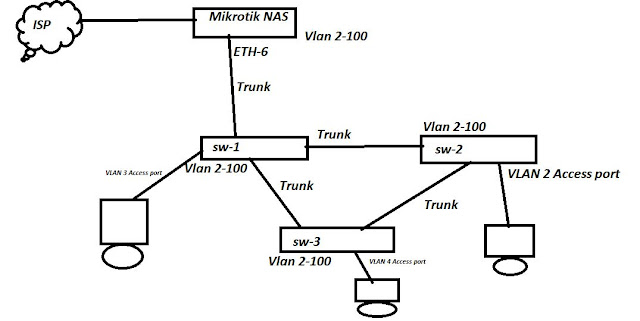
This is one of the most popular method  in ISP domain because most of the ISP's are using the VLAN in their network  . But there is some additional configuration required for this activity .We can configure the multiple Hotspot server in one physical interface using multiple VLAN and as you can see my picture below there is configured the LINK from mikrotik NAS to switch is trunk link and also I have allowed all the VLAN in that port .


Lets start the configuration .


Lets Start the configuration according to my scenario .


Configure the VLAN first in  Mikrotik .


Here , I have created  only 3 vlan for testing purpose but you can create up to 4096 VLAn in the Mikrotik .

Step-1

Click on Interface >VLAN>Add vlan(+)

/interface vlan
add interface=ether6 name=vlan2 vlan-id=2
add interface=ether6 name=vlan3 vlan-id=3

add interface=ether6 name=vlan4 vlan-id=4

Step-2

Configure The IP address in each VLAN.
Step-3 

Create the HOtspot server on VLAN interface .

I Have created 3 HOTspot servers for VLAN-2,3,4 . and in same way you you can create multiple HOtspot server under one physical interface using VLANs .


Apart from that , No need to change anything in the configuration end . everything would be same as my previous hotspot server configuration .


After completion of these things in the Mikrotik then  you have to create the VLAN(2-4) in cisco switch and the port should be configure the trunk between the switches .And you need to make the access port for providing the access to users .


You don't need to change anything at any where except these changes what I Did on my above picture .


Please find the below commands.

/interface vlan
add interface=ether6 name=VLAN2 vlan-id=2
add interface=ether6 name=VLAN3 vlan-id=3
add interface=ether6 name=VLAN4 vlan-id=4

/ip hotspot profile
set [ find default=yes ] login-by=http-chap,http-pap use-radius=yes
add hotspot-address=192.16.1.1 login-by=http-chap,http-pap name=hsprof1 \
    use-radius=yes

/ip pool

add name=VLAN2 ranges=11.0.0.2-11.0.0.254
add name=VLAN3 ranges=12.0.0.2-12.0.0.254
add name=VLAN4 ranges=13.0.0.2-13.0.0.254

/ip hotspot

add address-pool=VLAN2 disabled=no idle-timeout=none interface=VLAN2 name=\
    server1
add address-pool=VLAN3 disabled=no idle-timeout=none interface=VLAN3 name=\
    server2
add address-pool=VLAN4 disabled=no idle-timeout=none interface=VLAN4 name=\
    server3

/radius
add address=10.0.0.100 secret=secret service=ppp,hotspot timeout=9s

/radius incoming
set accept=yes

/ip address
add address=192.168.2.1/24 interface=VLAN2 network=192.168.2.0
add address=192.168.3.1/24 interface=VLAN3 network=192.168.3.0
add address=192.168.4.1/24 interface=VLAN4 network=192.168.4.0

/ip dns
set cache-size=10000KiB servers=8.8.4.4,8.8.8.8