Showing posts with label BGP. Show all posts

Thursday, 27 March 2025

Huawei 6720 Switch PBR Configuration

Note=The below configuration will not check the local routing table and it will forward all traffic to that nexthop..! 


[6720]acl number 3100

[6720-acl-adv-3100]rule 10 permit ip source 10.14.7.0 0.0.0.255


[6720]traffic classifier ABC

[6720-classifier-ABC]if-match acl 3100


[6720]traffic behavior ABC

[6720-behavior-ABC]redirect ip-nexthop 10.70.29.19


[6720]traffic policy ABC

Info: If the traffic policy has been applied to board, making modifications that are not supported by the board on the traffic policy may cause the failure to apply this traffic policy.

[6720-trafficpolicy-ABC]classifier ABC behavior ABC


[6720]traffic-policy ABC global inbound


Even if you configure it on interface still it will not check the local routing table and will forward all the traffic to that nexthop.


[6720]interface XGigabitEthernet 0/0/11

[6720-XGigabitEthernet0/0/11] traffic-policy ABC inbound


Here , i want that when there is a route not present in the routing table in that case the traffic will be forwarded to the nexthop only so i configured the acl to check the default route only..!


[6720]acl number 3100

[6720-acl-adv-3100]rule 10 permit ip source 110.14.7.0 0.0.0.255 destination 0.0.0.0 0.0.0.0


[6720]traffic-policy ABC global inbound

Interface Based PBR Configuration in Huawei Switch & Router..!

Policy-based routing PBR

Let’s assume that we have topology like this:

What we have to do is to force router CX_1 to choose interface G7/5/0 and next hop 10.0.2.2 to forward traffic from source IP 5.5.5.5 to destination IP 15.15.15.15. Rest of traffic should go through interface G7/5/7.

Configure IP addresses based on this topology.

Use OSPF protocol to ensure communication in tested network. Let’s take CX_1 as an example:

#
ospf 1 router-id 6.6.6.6
 area 0.0.0.0
  network 10.0.1.0 0.0.0.3
  network 10.0.2.0 0.0.0.3
  network 10.0.0.0 0.0.0.3
  network 6.6.6.6 0.0.0.0
#

Configure OSPF for the remaining routers.

Increase OSPF cost of one of the links between CX_1 and CX_2 to exclude load-balancing:

#
interface GigabitEthernet7/5/0
 ospf cost 100
#

Display routing-table of AR29 to check if all necessary subnets are available through OSPF (display ip routing-table).

Configure ACL on CX_1 which permits IP source 5.5.5.5 to send packets to destination IP 15.15.15.15:

[CX_1]acl number 3000
[CX_1-acl-3000}rule 5 permit ip source 5.5.5.5 0.0.0.0

Configure traffic classifier and traffic behavior for classified packets:

#
traffic classifier ABC
if-match acl 3000 # traffic behavior ABC
redirect ip-nexthop 10.0.2.2 interface GigabitEthernet7/5/0 #

Configure traffic policy and assign it to interface G7/5/5 as inbound:

#
traffic policy ABC
 statistics enable
 classifier ABC behavior ABC
# interface GigabitEthernet7/5/5 traffic-policy ABC inbound
#

Let’s check now what the result of such traffic policy is. On AR29 router we can use tracert command to check how traffic is going to 15.15.15.15.

<AR29>tracert -a 5.5.5.5 15.15.15.15
 traceroute to  15.15.15.15(15.15.15.15), max hops: 30, packet length: 40, press CTRL_C to break
1   10.0.0.1 4 ms  2 ms  7 ms
2   10.0.2.2 3 ms  4 ms  5 ms

As we can see traffic policy is working correctly choosing 10.0.2.2 as the IP next hop.

Now we can try the same but without source IP 5.5.5.5:

<AR29>tracert 15.15.15.15
 traceroute to  15.15.15.15(15.15.15.15), max hops: 30, packet length: 40, press CTRL_C to break
1   10.0.0.1 3 ms  1 ms  1 ms
2   10.0.1.2 3 ms  2 ms  2 ms

We can see that policy-based routing is working properly for traffic classified in ACL 3000. Rest of traffic is choosing a route based on IP routing table.

We can also check statistics for this traffic policy. We can use ping for such purposes. Use ping from AR29 and check statistics on CX_1:

<AR29>ping -a 5.5.5.5 -c 100 -m 100 15.15.15.15
<CX_1>display traffic policy statistics interface g 7/5/5 inbound
Info: The statistics is shared because the policy is shared.
Interface: GigabitEthernet7/5/5
Traffic policy inbound: labnario
Traffic policy applied at 2012-02-06 16:15:04
Statistics enabled at 2012-02-06 16:15:16
Statistics last cleared: 2012-02-06 20:14:59
Rule number: 4 IPv4, 0 IPv6
Current status: OK!
Item                             Packets                      Bytes
-------------------------------------------------------------------
Matched                              100                     10,200
  +--Passed                          100                     10,200
  +--Dropped                           0                          0
    +--Filter                          0                          0
    +--URPF                            0                          0
    +--CAR                             0                          0
Missed                                19                      2,640
Last 30 seconds rate
Item                                 pps                        bps
-------------------------------------------------------------------
Matched                                0                          0
  +--Passed                            0                          0
  +--Dropped                           0                          0
    +--Filter                          0                          0
    +--URPF                            0                          0
    +--CAR                             0                          0
Missed                                 0                        288
<AR29>ping -c 100 -m 100 15.15.15.15
<CX_1>dis traffic policy statistics interface g 7/5/5 inbound
Info: The statistics is shared because the policy is shared.
Interface: GigabitEthernet7/5/5
Traffic policy inbound: labnario
Traffic policy applied at 2012-02-06 16:15:04
Statistics enabled at 2012-02-06 16:15:16
Statistics last cleared: 2012-02-06 20:14:59
Rule number: 4 IPv4, 0 IPv6
Current status: OK!
Item                             Packets                      Bytes
-------------------------------------------------------------------
Matched                              100                     10,200
  +--Passed                          100                     10,200
  +--Dropped                           0                          0
    +--Filter                          0                          0
    +--URPF                            0                          0
    +--CAR                             0                          0
Missed                               126                     13,956
Last 30 seconds rate
Item                                 pps                        bps
-------------------------------------------------------------------
Matched                                0                          0
  +--Passed                            0                          0
  +--Dropped                           0                          0
    +--Filter                          0                          0
    +--URPF                            0                          0
    +--CAR                             0                          0
Missed                                 3                      2,648

You can also configure policy-based routing in MPLS L3VPN to allow some IP traffic (based on ACL) from one VPN to be redirected to another VPN. Maybe I will show you such configuration in the future.

Interface Based PBR Configuration in Huawei router..!


Step 1: As we verified the connectivity between PCs and the path taken by the traffic from PC2 to PC4 and PC3 to PC5.

Traffic from PC2 to PC4 passes through R4
Traffic from PC3 to PC5 also passes through R4.

The objective of this lab is to use Policy based routing to ensure traffic from PC2 to PC4 passes through R4 while traffic from PC3 to PC5 passes through R5.


Step 2: Configure ACLs to match traffic from PC2 and PC3 as follows on R3. We use extended ACLs to be able to match the source IP addresses.

***************************R3
#
acl number 3000
 rule 5 permit ip source 40.40.40.0 0.0.0.1
#
acl number 3002
 rule 5 permit ip source 50.50.50.0 0.0.0.1
#

Step 3: Configure PBR and apply it on the interfaces facing PCs on R3.

**************************R3
#
policy-based-route TEST_PBR permit node 5
 if-match acl 3000
 apply output-interface Serial0/0/0
policy-based-route TEST_PBR permit node 10
 if-match acl 3002
 apply output-interface Serial0/0/1
#
interface Ethernet0/0/0
 ip policy-based-route TEST_PBR
#
interface Ethernet0/0/1
 ip policy-based-route TEST_PBR
#

Step 4: Verify the path taken by traffic from PC2 and PC3.

Traffic from PC3 now follows the path through R5 and R7.

Note: The PBR configured on R3 doe not affect the path for the return traffic from PC4 and PC5. You must configure same PBR on R6 to be able to control the flow of the return traffic.

Return traffic from PC5 still goes through R4.

This is how you can use PBR to control traffic flow in your network. Thank You for reading and please leave your comments below. Check out other related articles on our page. 

HUawei Global PBR Configuration in Switch...!

 Traffic routing with Policy-based routing (PBR)

Packet routing is generally carried out by equipment by consulting its routing table where they look for the best routes based on their destination address.


However, what I intend to show is that there are other forms of packet routing, such as PBR, which allows routes to be changed based on other criteria such as source addresses, packet size or next hop.


To show one of the ways to configure packet forwarding based on PBR, I will use an example:


In the company we have two departments that have different access to the Internet due to the needs of the IT Team who need better access to the Internet. What we are going to show is a way to configure the routing of each network for its Internet access, and both teams access the DMZ and can also communicate with each other.


qrwrqr


The first step will be to carefully configure an ACL to select only the traffic we want to redirect. As we want to redirect all traffic destined for the Internet, we make the following configuration:


ACL name IT_TEAM number 3001

rule 10 permit ip source 192.168.0.0 0.0.0.255 destination any

rule 15 permit ip source 192.168.1.0 0.0.0.255 destination any

 #

ACL Name COM_TEAM number 3002

rule 10 permit ip source 192.168.2.0 0.0.0.255 destination any

rule 15 permit ip source 192.168.3.0 0.0.0.255 destination any 


After defining the ACLs, they configured the traffic classifiers


traffic classifier TC_IT_TEAM type or

  if-match acl 3001

 #

traffic classifier TC_COM_TEAM type or

  if-match acl 3002


The next step was to choose what to do with the traffic they had just categorized.


traffic behavior TB_IT_TEAM

redirect nexthop 192.168.0.147

 #

traffic behavior TB_COM_TEAM

redirect nexthop 192.168.0.149


As you know after the classifier and traffic behavior are configured they need to be put together to make sense. And that's what they did too.


traffic policy TP_IT_TEAM

classifier TC_IT_TEAM behavior TB_IT_TEAM

#

traffic policy TP_COM_TEAM

classifier TC_COM_TEAM behavior TB_COM_TEAM


Finally, the traffic policies were configured. The only thing left to do was to apply the traffic policies on the switch.


traffic-policy TP_IT_TEAM global inbound

#

traffic-policy TP_COM_TEAM global inbound


After that, traffic destined for the internet was redirected according to the policy.

Saturday, 7 December 2024

Huawei Port based Rate limit configuration..!--L3 Port

 Huawei Port based Rate limit configuration on routing port .


interface XGigabitEthernet0/0/21
 undo portswitch
 ipv6 enable
 ip address 10.050.5 255.255.255.252
 qos lr outbound cir 600000 cbs 620000
 qos lr inbound cir 600000 cbs 620000
#
return


Tuesday, 3 December 2024

Transit ISP bgp configuration..Only default route adverisement..!

In this blog, we will see how we will advertise only default route to our transit peer . find the diagram below.

bgp 456
 graceful-restart
 graceful-restart peer-reset
 undo check-first-as
 peer 10.10.1.2 as-number 789
peer 2XXX:XXX:XXX:2::2 as-number 789

 ipv4-family unicast
 peer 10.10.1.2 enable
  peer 10.10.1.2 route-policy ASN-789-IN import
  peer 10.10.1.2 route-policy ASN-789-OUT export
  peer 10.10.1.2 default-route-advertise


ipv6-family unicast
  undo synchronization
  peer 2XXX:XXX:XXX:X::2 enable
  peer 2XXX:XXX:XXX:X::2 route-policy ASN-789-IPv6-IN import
  peer 2XXX:XXX:XXX:X::2 route-policy ASN-789-IPv6-OUT export
  peer 2XXX:XXX:XXX:X::2 default-route-advertise


################Downlink IPv4 Route filtering configuration#############


ip ip-prefix ASN-789-OUT index 10 permit 0.0.0.0 0
ip ip-prefix ASN-789-IN index 11 permit 1XX.XXX.XXX.0 23


route-policy ASN-789-OUT permit node 20
 if-match ip-prefix ASN-789-OUT

route-policy ASN-789-IN permit node 20
 if-match ip-prefix ASN-789-IN

################Downlink IPv6 Route filtering configuration#############


ip ipv6-prefix ASN-789-IPV6-IN index 10 permit 2XXX:2XXX:: 32
ip ipv6-prefix ASN-789-IPV6-OUT index 10 permit :: 0


route-policy ASN-789-IPv6-OUT permit node 20
 if-match ipv6 address prefix-list ASN-789-IPV6-OUT
#
route-policy ASN-789-IPv6-IN permit node 20
 if-match ipv6 address prefix-list ASN-789-IPV6-IN
#


Monday, 11 November 2024

Transit ISP BGP Configuration...!


Introduction

The next step of this workshop lab will set up eBGP with our upstream provider so that we can see the Internet.


Lab Topology

The diagram below is a reminder of the lab topology:


The lab instructors will be running the routers for the two Transit Providers and will have already configured them. Please remember to discuss any problems with setting up BGP with the two Transit Operators. Don’t just assume that if eBGP doesn’t come up that the lab instructors will fix the problem for you in the background.


Follow the guidelines in the IP Address Plan document to configure the link to the upstream. Make sure that you can ping the upstream’s router using both IPv4 and IPv6 - if it doesn’t work, investigate why not.

Here is an typical configuration sample - note that we are following the same good practices as we did when we set up the internal interfaces on our network:

interface Fastethernet 0/0
 description Link to Transit Provider N
 ip address <ipv4-ptp> 255.255.255.252
 no ip directed-broadcast
 no ip redirects
 no ip proxy-arp
 ipv6 address <ipv6-ptp>/127
 ipv6 nd prefix default no-advertise
 ipv6 nd ra suppress all
 no shutdown
!


IS-IS

Do not configure IS-IS towards the upstream provider! They are not part of your autonomous system.


External BGP

We now configure eBGP with the upstream. Again, the configuration on the two transit routers will have already been completed by the instructors, so once configured, the eBGP session should just come up and work.

Don’t forget to filter what you hear from the upstream, and what you send to them. You should only accept a default route from them (they may send you more), and you should only send prefixes you originated!

Let’s set up the filters first, before we set up the eBGP session with our external neighbour. Let’s create an outbound filter for the prefixes we will send to our upstream provider. We do this for IPv4:

ip prefix-list ASX0-block permit 100.68.X.0/24

and IPv6:

ipv6 prefix-list ASX0-v6block permit 2001:DB8:X::/48

Now we need to create prefix-lists for the default route we are hearing from the upstream provider. First we create one for IPv4:

ip prefix-list DEFAULT-ROUTE permit 0.0.0.0/0

and then for IPv6:

ipv6 prefix-list DEFAULT-v6ROUTE permit ::/0

Then we can set up the eBGP configuration. Here is a configuration sample, first for IPv4:

router bgp X0
!
 address-family ipv4
  neighbor <ipv4-ptp> remote-as <N-ASN>
  neighbor <ipv4-ptp> description eBGP with TRANSIT N
  neighbor <ipv4-ptp> password BGPlab
  neighbor <ipv4-ptp> prefix-list ASX0-block out
  neighbor <ipv4-ptp> prefix-list DEFAULT-ROUTE in
  neighbor <ipv4-ptp> activate
!

and then for IPv6:

router bgp X0
!
 address-family ipv6
  neighbor <ipv6-ptp> remote-as <N-ASN>
  neighbor <ipv6-ptp> description eBGP with TRANSIT N
  neighbor <ipv6-ptp> password BGPlab
  neighbor <ipv6-ptp> prefix-list ASX0-v6block out
  neighbor <ipv6-ptp> prefix-list DEFAULT-v6ROUTE in
  neighbor <ipv6-ptp> activate
!

Once this has been configured, you should now see a default route coming from the upstream provider, and you should be able to see your aggregate being sent to your upstream.

If you see nothing from the upstream provider, check your filters first before asking the lab instructors. Check also with your lab instructors to make sure that they are seeing your IPv4 and IPv6 aggregates. Don’t just assume they will somehow look on your behalf.

The commands to see what you are receiving from the Transit Provider are:

show ip bgp neighbor <ipv4-ptp> routes
show bgp ipv6 unicast neighbor <ipv6-ptp> routes

and to show what you are sending to the Transit Provider:

show ip bgp neighbor <ipv4-ptp> advertised-routes
show bgp ipv6 unicast neighbor <ipv6-ptp> advertised-routes

Note that there are IPv4 versions of the IPv6 commands too, although they are a bit more to type than the versions given above:

show bgp ipv4 unicast neighbor <ipv4-ptp> routes
show bgp ipv4 unicast neighbor <ipv4-ptp> advertised-routes


Confirmation

Check on the Core, Access and Peering Routers what you now see in the BGP table. Are there differences? Can you explain what they are, and why?


Sending Default Route using IS-IS

The border router connects to the upstream provider, and therefore gives us access to the whole Internet. The upstream provider will usually send us a default route by eBGP. Once we hear this default route, how should it be propagated around the autonomous system?

It can be propagated using iBGP as we have just seen, but that tends to be non-optimal, certainly when trying to load balance between two or more transit providers, as the BGP best path is just that, the one and only best path. If we distribute the default by the IGP instead, then at least the default route becomes the nearest exit, to the nearest border router (we only have one in this lab, but a future scaled version of this network infrastructure would double up on the core, border and peering routers at least).

IS-IS by default will always originate a default route with the default-information originate command (unlike OSPF which will do it only if there is a default route in the Global RIB)1. So we need to fix this so that IS-IS will only announce a default if it sees the default in the Global RIB. To do this we will reuse the prefix-list we already created earlier which has the default route in it:

ip prefix-list DEFAULT-ROUTE permit 0.0.0.0/0
ipv6 prefix-list DEFAULT-v6ROUTE permit ::/0

Now we create a route-map which matches the default route, first for IPv4:

route-map DEFAULT-ORIG permit 5
 match ip address prefix-list DEFAULT-ROUTE
!

and then for IPv6 (using same name, but adding v6):

route-map DEFAULT-ORIGv6 permit 5
 match ipv6 address prefix-list DEFAULT-v6ROUTE
!

and finally we apply the route-map to the default-information originate command in IS-IS:

router isis asX0
 default-information originate route-map DEFAULT-ORIG
!
 address-family ipv6
  default-information originate route-map DEFAULT-ORIGv6
!


Confirmation

Check on the Core, Access and Peering Routers what you now see in the BGP table. And look at the Routing table on each. Are there differences? Can you explain what is happening now?


RIB Failure?

What does:

show ip bgp 0.0.0.0 0.0.0.0
show ip route 0.0.0.0 0.0.0.0

and

show ipv6 route ::/0
show bgp ipv6 unicast ::/0

show you on the core router and on the peering router?

You will notice that the default route is being propagated by BGP throughout the AS.

  • On the core and access routers, you should see “complaints” of a RIB failure when you look at the BGP table, because IS-IS has a default route with a lower protocol distance.

  • On the peering router, it will complain of a RIB failure when you look at the BGP table, because there is a static default route to the Null interface.

While there is nothing wrong with a RIB failure, we can just remove the default from being propagated by the iBGP process.


Stopping default route propagation by iBGP

To do this, we go back to the eBGP session with the transit provider (on the border router), look for the default, tag it with the no-advertise community, and then the border router will no longer announce the default by iBGP.

Let’s create the route-map first - we’ll have to create one for IPv4 and another one for IPv6. We already have a prefix-list for the default route on the Border router, so we can re-use it for the route-maps we are creating, First we create the IPv4 route-map:

route-map tag-default permit 5
 match ip address prefix-list DEFAULT-ROUTE
 set community no-advertise
!
route-map tag-default permit 10
!

and then we create the IPv6 version:

route-map tag-v6default permit 5
 match ipv6 address prefix-list DEFAULT-v6ROUTE
 set community no-advertise
!
route-map tag-v6default permit 10
!

And then we apply the route-maps to the Border router. Here is a configuration sample for the Border router:

router bgp X0
 address-family ipv4
  neighbor <ipv4-ptp> route-map tag-default in
!
 address-family ipv6
  neighbor <ipv6-ptp> route-map tag-v6default in
!

Once this is done, we need to refresh the iBGP session the Border router has with the Core router:

BX# clear ip bgp X0 out
BX# clear bgp ipv6 unicast X0 out

To confirm, has the default route now disappeared from the BGP table on the Core, Access and Peering routers? If not, check your configuration, check the route-refresh command you issued above.


Testing

Once this has been completed, test the connectivity. Can you reach the other groups in the class? You should be able to ping all the IPv4 and IPv6 loopbacks across the whole classroom.

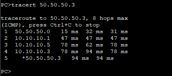
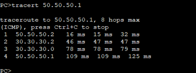
Can you see the Internet too? The lab has IPv4 connectivity to the Internet - check that this works by trying a few pings or traceroutes to well known destinations (e.g. to 8.8.8.8).

The instructors will let you know if the lab has IPv6 connectivity. If it does, check IPv6 connectivity to the Internet as well, by trying a few pings or traceroutes to well know destinations (e.g. to 2001:4860:4860::8888).

Hint: for the traceroutes, try using the loopback address as the source for your pings and traceroutes2.


Appendix - Transit Router Configuration

This appendix shows the minimum configuration used for the TR1 router in this lab. The TR2 router has a very similar configuration.

interface FastEthernet0/0
 description Link to AS10
 ip address 100.121.1.1 255.255.255.252
 ipv6 address 2001:18:0:10::/127
!
interface FastEthernet0/1
 description Link to AS20
 ip address 100.121.1.5 255.255.255.252
 ipv6 address 2001:18:0:11::/127
!
interface FastEthernet1/0
 description Link to AS30
 ip address 100.121.1.9 255.255.255.252
 ipv6 address 2001:18:0:12::/127
!
interface GigabitEthernet4/0
 description Link to TR2 (and to the world)
 ip address 100.121.0.1 255.255.255.252 secondary
 ip address 10.10.0.235 255.255.255.0
 ipv6 address 2001:18::/127
 ipv6 address 2001:DB8:100::235/64
!
router bgp 121
 bgp log-neighbor-changes
 bgp deterministic-med
 no bgp default ipv4-unicast
 neighbor 2001:18::1 remote-as 122
 neighbor 2001:18::1 description eBGP with TR2
 neighbor 2001:18::1 ttl-security hops 1
 neighbor 2001:18::1 password BGPlab
 neighbor 2001:18:0:10::1 remote-as 10
 neighbor 2001:18:0:10::1 password BGPlab
 neighbor 2001:18:0:11::1 remote-as 20
 neighbor 2001:18:0:11::1 password BGPlab
 neighbor 2001:18:0:12::1 remote-as 30
 neighbor 2001:18:0:12::1 password BGPlab
 neighbor 100.121.0.2 remote-as 122
 neighbor 100.121.0.2 description eBGP with TR2
 neighbor 100.121.0.2 ttl-security hops 1
 neighbor 100.121.0.2 password BGPlab
 neighbor 100.121.1.2 remote-as 10
 neighbor 100.121.1.2 password BGPlab
 neighbor 100.121.1.6 remote-as 20
 neighbor 100.121.1.6 password BGPlab
 neighbor 100.121.1.10 remote-as 30
 neighbor 100.121.1.10 password BGPlab
 !
 address-family ipv4
  network 100.121.0.0 mask 255.255.0.0
  neighbor 100.121.0.2 activate
  neighbor 100.121.1.2 activate
  neighbor 100.121.1.2 default-originate
  neighbor 100.121.1.6 activate
  neighbor 100.121.1.6 default-originate
  neighbor 100.121.1.10 activate
  neighbor 100.121.1.10 default-originate
  distance bgp 200 200 200
 exit-address-family
 !
 address-family ipv6
  network 2001:18::/32
  neighbor 2001:18::1 activate
  neighbor 2001:18:0:10::1 activate
  neighbor 2001:18:0:10::1 default-originate
  neighbor 2001:18:0:11::1 activate
  neighbor 2001:18:0:11::1 default-originate
  neighbor 2001:18:0:12::1 activate
  neighbor 2001:18:0:12::1 default-originate
  distance bgp 200 200 200
 exit-address-family
!
ip route 0.0.0.0 0.0.0.0 10.10.0.254
ip route 100.121.0.0 255.255.0.0 Null0
!
ipv6 route 2001:18::/32 Null0
ipv6 route ::/0 2001:DB8:100::241
!

  1. OSPF version of the command has a different result from the IS-IS version of the command. To conditionally announce the default in OSPF, default-information originate is sufficient. If the operator needs to always announce the default, regardless of whether it is in the Global RIB or not, the always keyword needs to be added.

  2. Can you explain why we are doing this, and not using the default (which would be the point-to-point link address of the outbound interface)?

Monday, 20 May 2024

What is AS Number and Why do we need it ??

 The Autonomous system is basically a kind of TAG which is basically going to represent an organization, You as an administrator are the in-charge of the routing domain  like routing policies, Routing protocols etc etc .

An autonomous system number (ASN) is a unique number, assigned by IANA that is available globally to identify an autonomous system and which enables that system to exchange exterior routing information with other neighboring autonomous systems.

ASN Types
There are two types of autonomous system numbers - public and private.

Public ASN - Used when an AS is exchanging routing information with other Autonomous Systems on the public Internet. 

Private ASN - Used if an AS is only required to communicate via Border Gateway Protocol with a single provider. As the routing policy between the AS and the provider will not be visible on the Internet. [3] In this case the upstream provider will typically remove the ASN from the ASN Path and replace it with his own public ASN. In reality, this can be thought of as a type of NAT for ASN`s.

ASN Ranges
Below lists the various ASN Ranges:
0 : reserved.
1-64,495 : public AS numbers.
64,496 – 64,511 : reserved to use in documentation.
64,512 – 65,534 : private AS numbers.
65,535 : reserved.

Tuesday, 30 April 2024

All You Need to Know About Prefix Lists..!

 The prefix list have been introduced speclfically for route / prefix filtering they allow to match a range of prefixes within an address block this is not easy to implement with an IP extended ACL and not all routing protocols support this use of IP extended ACL.


Example:

ip prefix-list EXAMPLE permit 10.100.0.0/16 ge 20 le 24

This means all prefixes within 10.100.0.0/16 with prefix length between 20 and 24 are accepted:

10.100.128.0/17 is not a match
10.100.20.0/24 is a match
10.100.21.128/25 is not a match
10.100.0.0/23 is a match

The most notable and important difference is that a prefix list allows you to filter networks based on their subnet mask. ACLs used in distribute list filter networks only by network addresses but they do not perform matching on subnet mask; in other words, for an ACL used in distribute list, the networks 192.168.10.0/24 and 192.168.10.0/28 are indistinguishable. Moreover, the prefix list also allows you to specify networks in a much more natural format than ACLs.


Example -1: How To Permit all the prefix.

ip prefix-list ALL-Networks permit 0.0.0.0/0 le 32


Example #2: How to block the prefix 11.0.0.0/24.


ip prefix-list DENY-11 deny 11.0.0.0/24

Due to the implicit deny of the prefix list, a second line is required to permit the other networks:

ip prefix-list DENY-11 permit 0.0.0.0/0 le 32

Note: the first line can be written like:

ip prefix-list DENY-11 deny 11.0.0.0/24 ge 24 le 24


Example #3: Permit only the default route

ip prefix-list DEFAULTE-ROUTE permit 0.0.0.0/0


Example #4: Permit all prefixes in the 11.0.0.0/16 with subnet mask less or equal /30

ip prefix-list TEST permit 11.0.0.0/16 le 30

this check the first 16 bits of the prefix 11.0.0.0, where the subnet mask must be less than or equal to 30.

So, if you have these networks:


11.0.0.0/24
11.11.11.0/24
11.0.11.128/30
11.0.0.10/32

Only the first and the third are valid. The second is not valid due to different prefix, while the fourth due to a greater subnet mask.


Example #5: Permits all prefixes in the 192.168.0.0/24 with subnet mask between 26 and 30 bits.


ip prefix-list TEST permit 192.168.0.0/24 ge 26 le 30


So, if you have these networks:

192.168.123.0/24
192.168.0.0/30
192.168.0.0/16
192.168.0.0/8


Only the second statement is valid; the third and fourth are not valid due to lesser subnet mask and the first one is not valid due the different network.


Example #6: Deny all the loopback network (/32)

ip prefix-list Test deny 0.0.0.0/0 ge 32 le 32


ip prefix-list Test permit 0.0.0.0/0 le 32


The first line block all the network with subnet mask /32, while the last line permit any.


How to stop advertising default route towards downstream BGP peer.#Prefixlist#Huawei

How to stop advertising the Default route towards your downstream BGP peer. Here is my diagram given below.


ISP Router Configuration Given Below.


Step-1 := Configure the Prefix-List.

#
ip ip-prefix BGP-NO-DEFAULT-ROUTE index 10 deny 0.0.0.0 0
ip ip-prefix BGP-NO-DEFAULT-ROUTE index 20 permit 0.0.0.0 0 less-equal 32
#

Step-2 := Configure the route-policy.


#
route-policy BGP-NO-DEFAULT-ROUTE permit node 10
 if-match ip-prefix BGP-NO-DEFAULT-ROUTE

Step-3 :=Apply On the peer .

#
  peer 10.1.22.34 route-policy BGP-NO-DEFAULT-ROUTE export
#
#