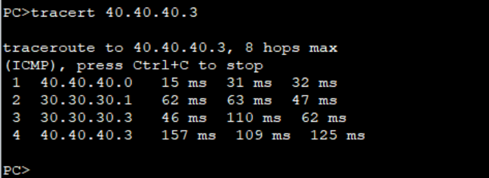
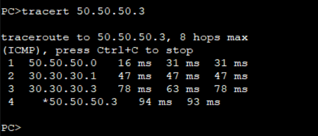
Step 1: As we verified the connectivity between PCs and the path taken by the traffic from PC2 to PC4 and PC3 to PC5.
Traffic from PC2 to PC4 passes through R4Traffic from PC3 to PC5 also passes through R4.
The objective of this lab is to use Policy based routing to ensure traffic from PC2 to PC4 passes through R4 while traffic from PC3 to PC5 passes through R5.
Step 2: Configure ACLs to match traffic from PC2 and PC3 as follows on R3. We use extended ACLs to be able to match the source IP addresses.
***************************R3
#
acl number 3000
 rule 5 permit ip source 40.40.40.0 0.0.0.1
#
acl number 3002
 rule 5 permit ip source 50.50.50.0 0.0.0.1
#
Step 3: Configure PBR and apply it on the interfaces facing PCs on R3.
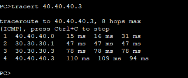
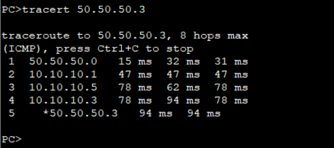
Step 4: Verify the path taken by traffic from PC2 and PC3.
Traffic from PC3 now follows the path through R5 and R7.
Note: The PBR configured on R3 doe not affect the path for the return traffic from PC4 and PC5. You must configure same PBR on R6 to be able to control the flow of the return traffic.
Return traffic from PC5 still goes through R4.
This is how you can use PBR to control traffic flow in your network. Thank You for reading and please leave your comments below. Check out other related articles on our page.
SW1#show spanning-tree bridge detail
VLAN0001
  Bridge ID  Priority    32769  (priority 32768 sys-id-ext 1)
             Address     5254.001a.935a
             Hello Time   2 sec  Max Age 20 sec  Forward Delay 15 sec
VLAN0010
  Bridge ID  Priority    32778  (priority 32768 sys-id-ext 10)
             Address     5254.001a.935a
             Hello Time   2 sec  Max Age 20 sec  Forward Delay 15 sec
VLAN0020
  Bridge ID  Priority    32788  (priority 32768 sys-id-ext 20)
             Address     5254.001a.935a
             Hello Time   2 sec  Max Age 20 sec  Forward Delay 15 sec
VLAN0030
  Bridge ID  Priority    32798  (priority 32768 sys-id-ext 30)
             Address     5254.001a.935a
             Hello Time   2 sec  Max Age 20 sec  Forward Delay 15 sec
SW2#show spanning-tree bridge detail
VLAN0001
  Bridge ID  Priority    32769  (priority 32768 sys-id-ext 1)
             Address     5254.0015.bc74
             Hello Time   2 sec  Max Age 20 sec  Forward Delay 15 sec
VLAN0010
  Bridge ID  Priority    32778  (priority 32768 sys-id-ext 10)
             Address     5254.0015.bc74
             Hello Time   2 sec  Max Age 20 sec  Forward Delay 15 sec
VLAN0020
  Bridge ID  Priority    32788  (priority 32768 sys-id-ext 20)
             Address     5254.0015.bc74
             Hello Time   2 sec  Max Age 20 sec  Forward Delay 15 sec
VLAN0030
  Bridge ID  Priority    32798  (priority 32768 sys-id-ext 30)
             Address     5254.0015.bc74
             Hello Time   2 sec  Max Age 20 sec  Forward Delay 15 sec
SW3#show spanning-tree bridge detail
VLAN0001
  Bridge ID  Priority    32769  (priority 32768 sys-id-ext 1)
             Address     5254.001d.e6bb
             Hello Time   2 sec  Max Age 20 sec  Forward Delay 15 sec
VLAN0010
  Bridge ID  Priority    32778  (priority 32768 sys-id-ext 10)
             Address     5254.001d.e6bb
             Hello Time   2 sec  Max Age 20 sec  Forward Delay 15 sec
VLAN0020
  Bridge ID  Priority    32788  (priority 32768 sys-id-ext 20)
             Address     5254.001d.e6bb
             Hello Time   2 sec  Max Age 20 sec  Forward Delay 15 sec
VLAN0030
  Bridge ID  Priority    32798  (priority 32768 sys-id-ext 30)
             Address     5254.001d.e6bb
             Hello Time   2 sec  Max Age 20 sec  Forward Delay 15 sec
The priority has a default value of 32768 so without configuring anything, the MAC address is the tie-breaker. In my case, SW2 is the root bridge for all VLANs:
SW2#show spanning-tree vlan 10

VLAN0010
  Spanning tree enabled protocol ieee
  Root ID    Priority    32778
             Address     5254.0015.bc74
             This bridge is the root
             Hello Time   2 sec  Max Age 20 sec  Forward Delay 15 sec

  Bridge ID  Priority    32778  (priority 32768 sys-id-ext 10)
             Address     5254.0015.bc74
             Hello Time   2 sec  Max Age 20 sec  Forward Delay 15 sec
             Aging Time  15  sec

Interface           Role Sts Cost      Prio.Nbr Type
------------------- ---- --- --------- -------- --------------------------------
Gi0/0               Desg FWD 4         128.1    P2p
Gi0/1               Desg FWD 4         128.2    P2p
SW2#show spanning-tree vlan 20

VLAN0020
  Spanning tree enabled protocol ieee
  Root ID    Priority    32788
             Address     5254.0015.bc74
             This bridge is the root
             Hello Time   2 sec  Max Age 20 sec  Forward Delay 15 sec

  Bridge ID  Priority    32788  (priority 32768 sys-id-ext 20)
             Address     5254.0015.bc74
             Hello Time   2 sec  Max Age 20 sec  Forward Delay 15 sec
             Aging Time  300 sec

Interface           Role Sts Cost      Prio.Nbr Type
------------------- ---- --- --------- -------- --------------------------------
Gi0/0               Desg FWD 4         128.1    P2p
Gi0/1               Desg FWD 4         128.2    P2p
SW2#show spanning-tree vlan 30

VLAN0030
  Spanning tree enabled protocol ieee
  Root ID    Priority    32798
             Address     5254.0015.bc74
             This bridge is the root
             Hello Time   2 sec  Max Age 20 sec  Forward Delay 15 sec

  Bridge ID  Priority    32798  (priority 32768 sys-id-ext 30)
             Address     5254.0015.bc74
             Hello Time   2 sec  Max Age 20 sec  Forward Delay 15 sec
             Aging Time  300 sec

Interface           Role Sts Cost      Prio.Nbr Type
------------------- ---- --- --------- -------- --------------------------------
Gi0/0               Desg FWD 4         128.1    P2p
Gi0/1               Desg FWD 4         128.2    P2p
Let’s see what we can do about that. I want to configure my network so it looks like this:
spanning-tree Configuration
We can change the root bridge for each VLAN with the spanning-tree Command. Here are our options:
SW1(config)#spanning-tree vlan 10 ?
  forward-time  Set the forward delay for the spanning tree
  hello-time    Set the hello interval for the spanning tree
  max-age       Set the max age interval for the spanning tree
  priority      Set the bridge priority for the spanning tree
  root          Configure switch as root
Above, we see two options:
priority: We can manually change the bridge priority.
root: We can configure the switch as root.
What’s the difference between these two parameters? Let’s find out.
The spanning-tree vlan command also accepts ranges of VLANs.
Root Parameter
We’ll start with the root parameter. Let’s check our options:
SW1(config)#spanning-tree vlan 10 root ?
  primary    Configure this switch as primary root for this spanning tree
  secondary  Configure switch as secondary root
I can configure the switch to become the primary or secondary root bridge. Let’s try primary:
SW1(config)#spanning-tree vlan 10 root primary
Let’s check whether that works:
SW1#show spanning-tree vlan 10

VLAN0010
  Spanning tree enabled protocol ieee
  Root ID    Priority    24586
             Address     5254.001a.935a
             This bridge is the root
             Hello Time   2 sec  Max Age 20 sec  Forward Delay 15 sec

  Bridge ID  Priority    24586  (priority 24576 sys-id-ext 10)
             Address     5254.001a.935a
             Hello Time   2 sec  Max Age 20 sec  Forward Delay 15 sec
             Aging Time  15  sec

Interface           Role Sts Cost      Prio.Nbr Type
------------------- ---- --- --------- -------- --------------------------------
Gi0/0               Desg FWD 4         128.1    P2p
Gi0/1               Desg FWD 4         128.2    P2p
In the output above, we see that SW1 is now the root bridge for VLAN 10. The priority of SW1 is now 24586.
We can also configure another switch to become the “secondary” root bridge. Let’s try that on SW2:
SW2(config)#spanning-tree vlan 10 root secondary
Let’s check what this command does:
SW2#show spanning-tree vlan 10

VLAN0010
  Spanning tree enabled protocol ieee
  Root ID    Priority    24586
             Address     5254.001a.935a
             Cost        4
             Port        1 (GigabitEthernet0/0)
             Hello Time   2 sec  Max Age 20 sec  Forward Delay 15 sec

  Bridge ID  Priority    28682  (priority 28672 sys-id-ext 10)
             Address     5254.0015.bc74
             Hello Time   2 sec  Max Age 20 sec  Forward Delay 15 sec
             Aging Time  300 sec

Interface           Role Sts Cost      Prio.Nbr Type
------------------- ---- --- --------- -------- --------------------------------
Gi0/0               Root FWD 4         128.1    P2p
Gi0/1               Desg FWD 4         128.2    P2p
Above, we see that the priority of SW2 is now 28682. In reality, there is no such thing as a “secondary” root bridge.
What happens is that behind the scenes,Cisco IOS sets a prioritywhen you use the root primary or root secondary parameters. We can verify this by looking at our configuration:
SW1#show running-config | include priority
spanning-tree vlan 10 priority 24576
SW2#show running-config | include priority
spanning-tree vlan 10 priority 28672
The way this works is that the switch looks at the priority of the current root bridge and then decreases its own priority so that it becomes the new root bridge.
Priority Parameter
We can also configure the priority manually like this:
SW2(config)#spanning-tree vlan 20 priority ?
  <0-61440>  bridge priority in increments of 4096
Let’s try that on SW2 for VLAN 20:
SW2(config)#spanning-tree vlan 20 priority 0
By setting the priority to 0, I’ll have the lowest possible priority. Let’s check whether SW2 is now the root bridge for VLAN 20:
SW2#show spanning-tree vlan 20

VLAN0020
  Spanning tree enabled protocol ieee
  Root ID    Priority    20
             Address     5254.0015.bc74
             This bridge is the root
             Hello Time   2 sec  Max Age 20 sec  Forward Delay 15 sec

  Bridge ID  Priority    20     (priority 0 sys-id-ext 20)
             Address     5254.0015.bc74
             Hello Time   2 sec  Max Age 20 sec  Forward Delay 15 sec
             Aging Time  300 sec

Interface           Role Sts Cost      Prio.Nbr Type
------------------- ---- --- --------- -------- --------------------------------
Gi0/0               Desg FWD 4         128.1    P2p
Gi0/1               Desg FWD 4         128.2    P2p
Above, we see that the priority is now 20 (priority 0 and sys-id-ext 20). Let’s configure SW3 to become the root bridge for VLAN 30:
SW3(config)#spanning-tree vlan 30 priority 0
Here’s the output of SW3:
SW3#show spanning-tree vlan 30

VLAN0030
  Spanning tree enabled protocol ieee
  Root ID    Priority    30
             Address     5254.001d.e6bb
             This bridge is the root
             Hello Time   2 sec  Max Age 20 sec  Forward Delay 15 sec

  Bridge ID  Priority    30     (priority 0 sys-id-ext 30)
             Address     5254.001d.e6bb
             Hello Time   2 sec  Max Age 20 sec  Forward Delay 15 sec
             Aging Time  300 sec

Interface           Role Sts Cost      Prio.Nbr Type
------------------- ---- --- --------- -------- --------------------------------
Gi0/0               Desg FWD 4         128.1    P2p
Gi0/1               Desg FWD 4         128.2    P2p
And as we can see above, SW3 is the root bridge for VLAN 30. That’s all there is to it.
Conclusion
You have now learned how to:
Verify the current root bridge per VLAN.
Configure the root bridge using the spanning-tree command:Using the root parameter.Using the priority parameter.
Let's say we will try on google.com. and we are not able to open the google.com website.
Step-1 = Ping to the website which is not opening.
First you have to check the ping to that website. There may be a possibility that ICMP is blocked in the destination end due to security concern...
C:\Users\hp>ping google.com Pinging google.com [142.250.194.206] with 32 bytes of data: Reply from 142.250.194.206: bytes=32 time=49ms TTL=58 Reply from 142.250.194.206: bytes=32 time=46ms TTL=58 Reply from 142.250.194.206: bytes=32 time=48ms TTL=58 Reply from 142.250.194.206: bytes=32 time=51ms TTL=58 Ping statistics for 142.250.194.206: Packets: Sent = 4, Received = 4, Lost = 0 (0% loss), Approximate round trip times in milli-seconds: Minimum = 46ms, Maximum = 51ms, Average = 48ms C:\Users\hp>
You can see above that ICMP is not blocked in google end and we are getting Ping to google.com.Thats Fine..
Till Now we are getting the ping but
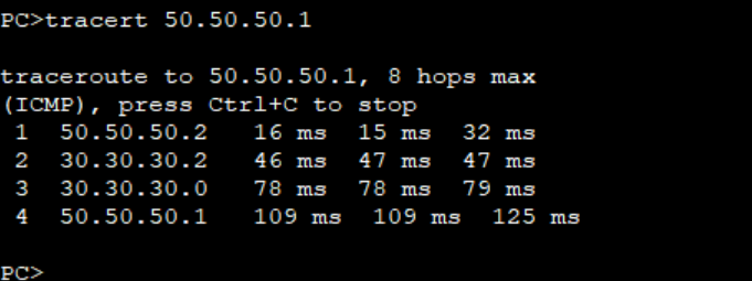
2-Check Traceroute to google.com to verify whether you can reach the destination or not .
C:\Users\hp>tracert google.com
Tracing route to google.com [142.250.193.206]
over a maximum of 30 hops:
1 1 ms 1 ms 1 ms 192.168.0.1
2 2 ms 1 ms 1 ms 103.14.9.18
3 43 ms 44 ms 42 ms 103.15.9.17
4 43 ms 43 ms 44 ms 103.6.9.26
5 46 ms 45 ms 46 ms 72.4.203.200
6 45 ms 46 ms 45 ms 142.250.244.151
7 45 ms 45 ms 45 ms 142.250.54.97
8 47 ms 44 ms 46 ms del11s17-in-f14.1e100.net [142.250.193.206]
Trace complete.
C:\Users\hp>
As you can see above that the Traceroute is showing OK and we are able to reach the destination.
Step-3=Check the DNS resolve , weather the DNS is proper or not .
As you can see above that DNS is working properly and we are able to resolve from name to IP and IP to name.
Step-4= Check the Telnet to Website whether the https://google.com is open on 443 port or not.
To check in Telenet , Got to your cmd and write the telnet google.com 443
C:\Users\hp>telnet google.com 443
You can see above that we are able to access the website on 443 port , it means everything is fine .
Summary.
Till now everything is fine from our end but still we are not able to access the website . So now you have to contact your ISP for checking this issue because this issue can be with your public IP or in ISP end there is some routing issue such as Assymetric routing or Routing failure in the transit etc etc..and also there is a possibility that somewhere in transit Your public IP address is blocked.
To configure the bandwidth shaping on L2 Interface you can go to interface configuration Mode on the switch port, and apply the srr-queue bandwidth limit command. Here's an example:
The 90 sets the outbound bandwidth limit on the port to 90 percent of the port speed. Since this is a 100-Mb port, this should limit the outbound traffic from the port to 10 Mb.
In this tutorial, i will show you how you can configure q-in-q L2 tunnel over the your transit L2 network for carrying the customer's internal vlan with any interference of your network vlan.
You as an ISP , you have to assign an unique vlan for each and every customer and that's up to the customer whatever the vlan they can carry .
lets see the configuration.
PE-1 Switch Configuration
# sysname PE-1 # vlan batch 2 to 3 # interface GigabitEthernet0/0/3 port link-type dot1q-tunnel port default vlan 2 # interface GigabitEthernet0/0/1 port link-type dot1q-tunnel port default vlan 3 # interface GigabitEthernet0/0/2 qinq protocol 9100 port link-type trunk port trunk allow-pass vlan 2 3 # return
PE-2 Switch Configuration
# sysname PE-2 # vlan batch 2 to 3 # interface GigabitEthernet0/0/1 port link-type dot1q-tunnel port default vlan 2 # interface GigabitEthernet0/0/3 port link-type dot1q-tunnel port default vlan 3 # interface GigabitEthernet0/0/2 qinq protocol 9100 port link-type trunk port trunk allow-pass vlan 2 3 # return