Info: If the traffic policy has been applied to board, making modifications that are not supported by the board on the traffic policy may cause the failure to apply this traffic policy.
Here , i want that when there is a route not present in the routing table in that case the traffic will be forwarded to the nexthop only so i configured the acl to check the default route only..!
[6720]acl number 3100
[6720-acl-adv-3100]rule 10 permit ip source 110.14.7.0 0.0.0.255 destination 0.0.0.0 0.0.0.0
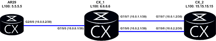
What we have to do is to force router CX_1 to choose interface G7/5/0 and next hop 10.0.2.2 to forward traffic from source IP 5.5.5.5 to destination IP 15.15.15.15. Rest of traffic should go through interface G7/5/7.
Configure IP addresses based on this topology.
Use OSPF protocol to ensure communication in tested network. Let’s take CX_1 as an example:
Let’s check now what the result of such traffic policy is. On AR29 router we can use tracert command to check how traffic is going to 15.15.15.15.
<AR29>tracert -a 5.5.5.5 15.15.15.15
 traceroute to  15.15.15.15(15.15.15.15), max hops: 30, packet length: 40, press CTRL_C to break
1   10.0.0.1 4 ms  2 ms  7 ms
2   10.0.2.2 3 ms  4 ms  5 ms
As we can see traffic policy is working correctly choosing 10.0.2.2 as the IP next hop.
Now we can try the same but without source IP 5.5.5.5:
<AR29>tracert 15.15.15.15
 traceroute to  15.15.15.15(15.15.15.15), max hops: 30, packet length: 40, press CTRL_C to break
1   10.0.0.1 3 ms  1 ms  1 ms
2   10.0.1.2 3 ms  2 ms  2 ms
We can see that policy-based routing is working properly for traffic classified in ACL 3000. Rest of traffic is choosing a route based on IP routing table.
We can also check statistics for this traffic policy. We can use ping for such purposes. Use ping from AR29 and check statistics on CX_1:
<AR29>ping -a 5.5.5.5 -c 100 -m 100 15.15.15.15
<CX_1>display traffic policy statistics interface g 7/5/5 inbound
Info: The statistics is shared because the policy is shared.
Interface: GigabitEthernet7/5/5
Traffic policy inbound: labnario
Traffic policy applied at 2012-02-06 16:15:04
Statistics enabled at 2012-02-06 16:15:16
Statistics last cleared: 2012-02-06 20:14:59
Rule number: 4 IPv4, 0 IPv6
Current status: OK!
Item                             Packets                      Bytes
-------------------------------------------------------------------
Matched                              100                     10,200
  +--Passed                          100                     10,200
  +--Dropped                           0                          0
    +--Filter                          0                          0
    +--URPF                            0                          0
    +--CAR                             0                          0
Missed                                19                      2,640
Last 30 seconds rate
Item                                 pps                        bps
-------------------------------------------------------------------
Matched                                0                          0
  +--Passed                            0                          0
  +--Dropped                           0                          0
    +--Filter                          0                          0
    +--URPF                            0                          0
    +--CAR                             0                          0
Missed                                 0                        288
<AR29>ping -c 100 -m 100 15.15.15.15
<CX_1>dis traffic policy statistics interface g 7/5/5 inbound
Info: The statistics is shared because the policy is shared.
Interface: GigabitEthernet7/5/5
Traffic policy inbound: labnario
Traffic policy applied at 2012-02-06 16:15:04
Statistics enabled at 2012-02-06 16:15:16
Statistics last cleared: 2012-02-06 20:14:59
Rule number: 4 IPv4, 0 IPv6
Current status: OK!
Item                             Packets                      Bytes
-------------------------------------------------------------------
Matched                              100                     10,200
  +--Passed                          100                     10,200
  +--Dropped                           0                          0
    +--Filter                          0                          0
    +--URPF                            0                          0
    +--CAR                             0                          0
Missed                               126                     13,956
Last 30 seconds rate
Item                                 pps                        bps
-------------------------------------------------------------------
Matched                                0                          0
  +--Passed                            0                          0
  +--Dropped                           0                          0
    +--Filter                          0                          0
    +--URPF                            0                          0
    +--CAR                             0                          0
Missed                                 3                      2,648
You can also configure policy-based routing in MPLS L3VPN to allow some IP traffic (based on ACL) from one VPN to be redirected to another VPN. Maybe I will show you such configuration in the future.
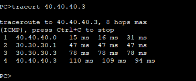
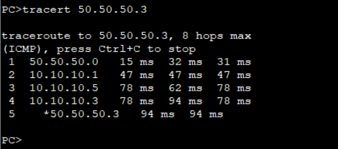
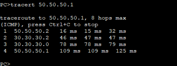
Step 1: As we verified the connectivity between PCs and the path taken by the traffic from PC2 to PC4 and PC3 to PC5.
Traffic from PC2 to PC4 passes through R4Traffic from PC3 to PC5 also passes through R4.
The objective of this lab is to use Policy based routing to ensure traffic from PC2 to PC4 passes through R4 while traffic from PC3 to PC5 passes through R5.
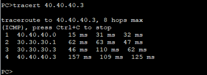
Step 2: Configure ACLs to match traffic from PC2 and PC3 as follows on R3. We use extended ACLs to be able to match the source IP addresses.
***************************R3
#
acl number 3000
rule 5 permit ip source 40.40.40.0 0.0.0.1
#
acl number 3002
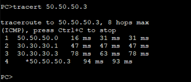
rule 5 permit ip source 50.50.50.0 0.0.0.1
#
Step 3: Configure PBR and apply it on the interfaces facing PCs on R3.
Step 4: Verify the path taken by traffic from PC2 and PC3.
Traffic from PC3 now follows the path through R5 and R7.
Note: The PBR configured on R3 doe not affect the path for the return traffic from PC4 and PC5. You must configure same PBR on R6 to be able to control the flow of the return traffic.
Return traffic from PC5 still goes through R4.
This is how you can use PBR to control traffic flow in your network. Thank You for reading and please leave your comments below. Check out other related articles on our page.
SW1#show spanning-tree bridge detail
VLAN0001
  Bridge ID  Priority    32769  (priority 32768 sys-id-ext 1)
             Address     5254.001a.935a
             Hello Time   2 sec  Max Age 20 sec  Forward Delay 15 sec
VLAN0010
  Bridge ID  Priority    32778  (priority 32768 sys-id-ext 10)
             Address     5254.001a.935a
             Hello Time   2 sec  Max Age 20 sec  Forward Delay 15 sec
VLAN0020
  Bridge ID  Priority    32788  (priority 32768 sys-id-ext 20)
             Address     5254.001a.935a
             Hello Time   2 sec  Max Age 20 sec  Forward Delay 15 sec
VLAN0030
  Bridge ID  Priority    32798  (priority 32768 sys-id-ext 30)
             Address     5254.001a.935a
             Hello Time   2 sec  Max Age 20 sec  Forward Delay 15 sec
SW2#show spanning-tree bridge detail
VLAN0001
  Bridge ID  Priority    32769  (priority 32768 sys-id-ext 1)
             Address     5254.0015.bc74
             Hello Time   2 sec  Max Age 20 sec  Forward Delay 15 sec
VLAN0010
  Bridge ID  Priority    32778  (priority 32768 sys-id-ext 10)
             Address     5254.0015.bc74
             Hello Time   2 sec  Max Age 20 sec  Forward Delay 15 sec
VLAN0020
  Bridge ID  Priority    32788  (priority 32768 sys-id-ext 20)
             Address     5254.0015.bc74
             Hello Time   2 sec  Max Age 20 sec  Forward Delay 15 sec
VLAN0030
  Bridge ID  Priority    32798  (priority 32768 sys-id-ext 30)
             Address     5254.0015.bc74
             Hello Time   2 sec  Max Age 20 sec  Forward Delay 15 sec
SW3#show spanning-tree bridge detail
VLAN0001
  Bridge ID  Priority    32769  (priority 32768 sys-id-ext 1)
             Address     5254.001d.e6bb
             Hello Time   2 sec  Max Age 20 sec  Forward Delay 15 sec
VLAN0010
  Bridge ID  Priority    32778  (priority 32768 sys-id-ext 10)
             Address     5254.001d.e6bb
             Hello Time   2 sec  Max Age 20 sec  Forward Delay 15 sec
VLAN0020
  Bridge ID  Priority    32788  (priority 32768 sys-id-ext 20)
             Address     5254.001d.e6bb
             Hello Time   2 sec  Max Age 20 sec  Forward Delay 15 sec
VLAN0030
  Bridge ID  Priority    32798  (priority 32768 sys-id-ext 30)
             Address     5254.001d.e6bb
             Hello Time   2 sec  Max Age 20 sec  Forward Delay 15 sec
The priority has a default value of 32768 so without configuring anything, the MAC address is the tie-breaker. In my case, SW2 is the root bridge for all VLANs:
SW2#show spanning-tree vlan 10

VLAN0010
  Spanning tree enabled protocol ieee
  Root ID    Priority    32778
             Address     5254.0015.bc74
             This bridge is the root
             Hello Time   2 sec  Max Age 20 sec  Forward Delay 15 sec

  Bridge ID  Priority    32778  (priority 32768 sys-id-ext 10)
             Address     5254.0015.bc74
             Hello Time   2 sec  Max Age 20 sec  Forward Delay 15 sec
             Aging Time  15  sec

Interface           Role Sts Cost      Prio.Nbr Type
------------------- ---- --- --------- -------- --------------------------------
Gi0/0               Desg FWD 4         128.1    P2p
Gi0/1               Desg FWD 4         128.2    P2p
SW2#show spanning-tree vlan 20

VLAN0020
  Spanning tree enabled protocol ieee
  Root ID    Priority    32788
             Address     5254.0015.bc74
             This bridge is the root
             Hello Time   2 sec  Max Age 20 sec  Forward Delay 15 sec

  Bridge ID  Priority    32788  (priority 32768 sys-id-ext 20)
             Address     5254.0015.bc74
             Hello Time   2 sec  Max Age 20 sec  Forward Delay 15 sec
             Aging Time  300 sec

Interface           Role Sts Cost      Prio.Nbr Type
------------------- ---- --- --------- -------- --------------------------------
Gi0/0               Desg FWD 4         128.1    P2p
Gi0/1               Desg FWD 4         128.2    P2p
SW2#show spanning-tree vlan 30

VLAN0030
  Spanning tree enabled protocol ieee
  Root ID    Priority    32798
             Address     5254.0015.bc74
             This bridge is the root
             Hello Time   2 sec  Max Age 20 sec  Forward Delay 15 sec

  Bridge ID  Priority    32798  (priority 32768 sys-id-ext 30)
             Address     5254.0015.bc74
             Hello Time   2 sec  Max Age 20 sec  Forward Delay 15 sec
             Aging Time  300 sec

Interface           Role Sts Cost      Prio.Nbr Type
------------------- ---- --- --------- -------- --------------------------------
Gi0/0               Desg FWD 4         128.1    P2p
Gi0/1               Desg FWD 4         128.2    P2p
Let’s see what we can do about that. I want to configure my network so it looks like this:
spanning-tree Configuration
We can change the root bridge for each VLAN with the spanning-tree Command. Here are our options:
SW1(config)#spanning-tree vlan 10 ?
  forward-time  Set the forward delay for the spanning tree
  hello-time    Set the hello interval for the spanning tree
  max-age       Set the max age interval for the spanning tree
  priority      Set the bridge priority for the spanning tree
  root          Configure switch as root
Above, we see two options:
priority: We can manually change the bridge priority.
root: We can configure the switch as root.
What’s the difference between these two parameters? Let’s find out.
The spanning-tree vlan command also accepts ranges of VLANs.
Root Parameter
We’ll start with the root parameter. Let’s check our options:
SW1(config)#spanning-tree vlan 10 root ?
  primary    Configure this switch as primary root for this spanning tree
  secondary  Configure switch as secondary root
I can configure the switch to become the primary or secondary root bridge. Let’s try primary:
SW1(config)#spanning-tree vlan 10 root primary
Let’s check whether that works:
SW1#show spanning-tree vlan 10

VLAN0010
  Spanning tree enabled protocol ieee
  Root ID    Priority    24586
             Address     5254.001a.935a
             This bridge is the root
             Hello Time   2 sec  Max Age 20 sec  Forward Delay 15 sec

  Bridge ID  Priority    24586  (priority 24576 sys-id-ext 10)
             Address     5254.001a.935a
             Hello Time   2 sec  Max Age 20 sec  Forward Delay 15 sec
             Aging Time  15  sec

Interface           Role Sts Cost      Prio.Nbr Type
------------------- ---- --- --------- -------- --------------------------------
Gi0/0               Desg FWD 4         128.1    P2p
Gi0/1               Desg FWD 4         128.2    P2p
In the output above, we see that SW1 is now the root bridge for VLAN 10. The priority of SW1 is now 24586.
We can also configure another switch to become the “secondary” root bridge. Let’s try that on SW2:
SW2(config)#spanning-tree vlan 10 root secondary
Let’s check what this command does:
SW2#show spanning-tree vlan 10

VLAN0010
  Spanning tree enabled protocol ieee
  Root ID    Priority    24586
             Address     5254.001a.935a
             Cost        4
             Port        1 (GigabitEthernet0/0)
             Hello Time   2 sec  Max Age 20 sec  Forward Delay 15 sec

  Bridge ID  Priority    28682  (priority 28672 sys-id-ext 10)
             Address     5254.0015.bc74
             Hello Time   2 sec  Max Age 20 sec  Forward Delay 15 sec
             Aging Time  300 sec

Interface           Role Sts Cost      Prio.Nbr Type
------------------- ---- --- --------- -------- --------------------------------
Gi0/0               Root FWD 4         128.1    P2p
Gi0/1               Desg FWD 4         128.2    P2p
Above, we see that the priority of SW2 is now 28682. In reality, there is no such thing as a “secondary” root bridge.
What happens is that behind the scenes,Cisco IOS sets a prioritywhen you use the root primary or root secondary parameters. We can verify this by looking at our configuration:
SW1#show running-config | include priority
spanning-tree vlan 10 priority 24576
SW2#show running-config | include priority
spanning-tree vlan 10 priority 28672
The way this works is that the switch looks at the priority of the current root bridge and then decreases its own priority so that it becomes the new root bridge.
Priority Parameter
We can also configure the priority manually like this:
SW2(config)#spanning-tree vlan 20 priority ?
  <0-61440>  bridge priority in increments of 4096
Let’s try that on SW2 for VLAN 20:
SW2(config)#spanning-tree vlan 20 priority 0
By setting the priority to 0, I’ll have the lowest possible priority. Let’s check whether SW2 is now the root bridge for VLAN 20:
SW2#show spanning-tree vlan 20

VLAN0020
  Spanning tree enabled protocol ieee
  Root ID    Priority    20
             Address     5254.0015.bc74
             This bridge is the root
             Hello Time   2 sec  Max Age 20 sec  Forward Delay 15 sec

  Bridge ID  Priority    20     (priority 0 sys-id-ext 20)
             Address     5254.0015.bc74
             Hello Time   2 sec  Max Age 20 sec  Forward Delay 15 sec
             Aging Time  300 sec

Interface           Role Sts Cost      Prio.Nbr Type
------------------- ---- --- --------- -------- --------------------------------
Gi0/0               Desg FWD 4         128.1    P2p
Gi0/1               Desg FWD 4         128.2    P2p
Above, we see that the priority is now 20 (priority 0 and sys-id-ext 20). Let’s configure SW3 to become the root bridge for VLAN 30:
SW3(config)#spanning-tree vlan 30 priority 0
Here’s the output of SW3:
SW3#show spanning-tree vlan 30

VLAN0030
  Spanning tree enabled protocol ieee
  Root ID    Priority    30
             Address     5254.001d.e6bb
             This bridge is the root
             Hello Time   2 sec  Max Age 20 sec  Forward Delay 15 sec

  Bridge ID  Priority    30     (priority 0 sys-id-ext 30)
             Address     5254.001d.e6bb
             Hello Time   2 sec  Max Age 20 sec  Forward Delay 15 sec
             Aging Time  300 sec

Interface           Role Sts Cost      Prio.Nbr Type
------------------- ---- --- --------- -------- --------------------------------
Gi0/0               Desg FWD 4         128.1    P2p
Gi0/1               Desg FWD 4         128.2    P2p
And as we can see above, SW3 is the root bridge for VLAN 30. That’s all there is to it.
Conclusion
You have now learned how to:
Verify the current root bridge per VLAN.
Configure the root bridge using the spanning-tree command:Using the root parameter.Using the priority parameter.
There is some bug in libre NMS i found that suddenly my pooling has been stopped without any reason. SO to re run it i just rerun my daily.sh and validated the php to rerun it .
[root@localhost ~]# su - librenms [librenms@localhost ~]$ ./validate.php =========================================== Component | Version --------- | ------- LibreNMS | 24.8.0-72-g7d450345d (2024-09-15T05:43:11+05:30) DB Schema | 2024_08_27_182000_ports_statistics_table_rev_length (299) PHP | 8.1.21 Python | 3.6.8 Database | MariaDB 10.3.28-MariaDB RRDTool | 1.7.0 SNMP | 5.8 =========================================== [OK] Composer Version: 2.7.9 [OK] Dependencies up-to-date. [OK] Database connection successful [OK] Database connection successful [OK] Database Schema is current [OK] SQL Server meets minimum requirements [OK] lower_case_table_names is enabled [OK] MySQL engine is optimal [OK] Database and column collations are correct [OK] Database schema correct [OK] MySQL and PHP time match [OK] Active pollers found [OK] Dispatcher Service not detected [OK] Locks are functional [OK] Python poller wrapper is polling [OK] Redis is unavailable [OK] rrd_dir is writable [OK] rrdtool version ok [WARN] Your install is over 24 hours out of date, last update: Sun, 15 Sep 2024 00:13:11 +0000 [FIX]: Make sure your daily.sh cron is running and run ./daily.sh by hand to see if there are any errors.
[librenms@localhost ~]$ [librenms@localhost /]$ su root Password: [root@localhost /]# cd opt/librenms/ [root@localhost librenms]# sudo ./daily.sh Re-running /opt/librenms/daily.sh as librenms user Updating to latest codebase OK Updating Composer packages OK Updated from 7d450345d to 7034fd7a4 OK Updating SQL-Schema OK Updating submodules OK Cleaning up DB OK Fetching notifications OK Caching PeeringDB data OK [root@localhost librenms]#