Showing posts with label Huawei. Show all posts

Thursday, 27 March 2025

Huawei 6720 Switch PBR Configuration

Note=The below configuration will not check the local routing table and it will forward all traffic to that nexthop..! 


[6720]acl number 3100

[6720-acl-adv-3100]rule 10 permit ip source 10.14.7.0 0.0.0.255


[6720]traffic classifier ABC

[6720-classifier-ABC]if-match acl 3100


[6720]traffic behavior ABC

[6720-behavior-ABC]redirect ip-nexthop 10.70.29.19


[6720]traffic policy ABC

Info: If the traffic policy has been applied to board, making modifications that are not supported by the board on the traffic policy may cause the failure to apply this traffic policy.

[6720-trafficpolicy-ABC]classifier ABC behavior ABC


[6720]traffic-policy ABC global inbound


Even if you configure it on interface still it will not check the local routing table and will forward all the traffic to that nexthop.


[6720]interface XGigabitEthernet 0/0/11

[6720-XGigabitEthernet0/0/11] traffic-policy ABC inbound


Here , i want that when there is a route not present in the routing table in that case the traffic will be forwarded to the nexthop only so i configured the acl to check the default route only..!


[6720]acl number 3100

[6720-acl-adv-3100]rule 10 permit ip source 110.14.7.0 0.0.0.255 destination 0.0.0.0 0.0.0.0


[6720]traffic-policy ABC global inbound

Interface Based PBR Configuration in Huawei Switch & Router..!

Policy-based routing PBR

Let’s assume that we have topology like this:

What we have to do is to force router CX_1 to choose interface G7/5/0 and next hop 10.0.2.2 to forward traffic from source IP 5.5.5.5 to destination IP 15.15.15.15. Rest of traffic should go through interface G7/5/7.

Configure IP addresses based on this topology.

Use OSPF protocol to ensure communication in tested network. Let’s take CX_1 as an example:

#
ospf 1 router-id 6.6.6.6
 area 0.0.0.0
  network 10.0.1.0 0.0.0.3
  network 10.0.2.0 0.0.0.3
  network 10.0.0.0 0.0.0.3
  network 6.6.6.6 0.0.0.0
#

Configure OSPF for the remaining routers.

Increase OSPF cost of one of the links between CX_1 and CX_2 to exclude load-balancing:

#
interface GigabitEthernet7/5/0
 ospf cost 100
#

Display routing-table of AR29 to check if all necessary subnets are available through OSPF (display ip routing-table).

Configure ACL on CX_1 which permits IP source 5.5.5.5 to send packets to destination IP 15.15.15.15:

[CX_1]acl number 3000
[CX_1-acl-3000}rule 5 permit ip source 5.5.5.5 0.0.0.0

Configure traffic classifier and traffic behavior for classified packets:

#
traffic classifier ABC
if-match acl 3000 # traffic behavior ABC
redirect ip-nexthop 10.0.2.2 interface GigabitEthernet7/5/0 #

Configure traffic policy and assign it to interface G7/5/5 as inbound:

#
traffic policy ABC
 statistics enable
 classifier ABC behavior ABC
# interface GigabitEthernet7/5/5 traffic-policy ABC inbound
#

Let’s check now what the result of such traffic policy is. On AR29 router we can use tracert command to check how traffic is going to 15.15.15.15.

<AR29>tracert -a 5.5.5.5 15.15.15.15
 traceroute to  15.15.15.15(15.15.15.15), max hops: 30, packet length: 40, press CTRL_C to break
1   10.0.0.1 4 ms  2 ms  7 ms
2   10.0.2.2 3 ms  4 ms  5 ms

As we can see traffic policy is working correctly choosing 10.0.2.2 as the IP next hop.

Now we can try the same but without source IP 5.5.5.5:

<AR29>tracert 15.15.15.15
 traceroute to  15.15.15.15(15.15.15.15), max hops: 30, packet length: 40, press CTRL_C to break
1   10.0.0.1 3 ms  1 ms  1 ms
2   10.0.1.2 3 ms  2 ms  2 ms

We can see that policy-based routing is working properly for traffic classified in ACL 3000. Rest of traffic is choosing a route based on IP routing table.

We can also check statistics for this traffic policy. We can use ping for such purposes. Use ping from AR29 and check statistics on CX_1:

<AR29>ping -a 5.5.5.5 -c 100 -m 100 15.15.15.15
<CX_1>display traffic policy statistics interface g 7/5/5 inbound
Info: The statistics is shared because the policy is shared.
Interface: GigabitEthernet7/5/5
Traffic policy inbound: labnario
Traffic policy applied at 2012-02-06 16:15:04
Statistics enabled at 2012-02-06 16:15:16
Statistics last cleared: 2012-02-06 20:14:59
Rule number: 4 IPv4, 0 IPv6
Current status: OK!
Item                             Packets                      Bytes
-------------------------------------------------------------------
Matched                              100                     10,200
  +--Passed                          100                     10,200
  +--Dropped                           0                          0
    +--Filter                          0                          0
    +--URPF                            0                          0
    +--CAR                             0                          0
Missed                                19                      2,640
Last 30 seconds rate
Item                                 pps                        bps
-------------------------------------------------------------------
Matched                                0                          0
  +--Passed                            0                          0
  +--Dropped                           0                          0
    +--Filter                          0                          0
    +--URPF                            0                          0
    +--CAR                             0                          0
Missed                                 0                        288
<AR29>ping -c 100 -m 100 15.15.15.15
<CX_1>dis traffic policy statistics interface g 7/5/5 inbound
Info: The statistics is shared because the policy is shared.
Interface: GigabitEthernet7/5/5
Traffic policy inbound: labnario
Traffic policy applied at 2012-02-06 16:15:04
Statistics enabled at 2012-02-06 16:15:16
Statistics last cleared: 2012-02-06 20:14:59
Rule number: 4 IPv4, 0 IPv6
Current status: OK!
Item                             Packets                      Bytes
-------------------------------------------------------------------
Matched                              100                     10,200
  +--Passed                          100                     10,200
  +--Dropped                           0                          0
    +--Filter                          0                          0
    +--URPF                            0                          0
    +--CAR                             0                          0
Missed                               126                     13,956
Last 30 seconds rate
Item                                 pps                        bps
-------------------------------------------------------------------
Matched                                0                          0
  +--Passed                            0                          0
  +--Dropped                           0                          0
    +--Filter                          0                          0
    +--URPF                            0                          0
    +--CAR                             0                          0
Missed                                 3                      2,648

You can also configure policy-based routing in MPLS L3VPN to allow some IP traffic (based on ACL) from one VPN to be redirected to another VPN. Maybe I will show you such configuration in the future.

HUawei Global PBR Configuration in Switch...!

 Traffic routing with Policy-based routing (PBR)

Packet routing is generally carried out by equipment by consulting its routing table where they look for the best routes based on their destination address.


However, what I intend to show is that there are other forms of packet routing, such as PBR, which allows routes to be changed based on other criteria such as source addresses, packet size or next hop.


To show one of the ways to configure packet forwarding based on PBR, I will use an example:


In the company we have two departments that have different access to the Internet due to the needs of the IT Team who need better access to the Internet. What we are going to show is a way to configure the routing of each network for its Internet access, and both teams access the DMZ and can also communicate with each other.


qrwrqr


The first step will be to carefully configure an ACL to select only the traffic we want to redirect. As we want to redirect all traffic destined for the Internet, we make the following configuration:


ACL name IT_TEAM number 3001

rule 10 permit ip source 192.168.0.0 0.0.0.255 destination any

rule 15 permit ip source 192.168.1.0 0.0.0.255 destination any

 #

ACL Name COM_TEAM number 3002

rule 10 permit ip source 192.168.2.0 0.0.0.255 destination any

rule 15 permit ip source 192.168.3.0 0.0.0.255 destination any 


After defining the ACLs, they configured the traffic classifiers


traffic classifier TC_IT_TEAM type or

  if-match acl 3001

 #

traffic classifier TC_COM_TEAM type or

  if-match acl 3002


The next step was to choose what to do with the traffic they had just categorized.


traffic behavior TB_IT_TEAM

redirect nexthop 192.168.0.147

 #

traffic behavior TB_COM_TEAM

redirect nexthop 192.168.0.149


As you know after the classifier and traffic behavior are configured they need to be put together to make sense. And that's what they did too.


traffic policy TP_IT_TEAM

classifier TC_IT_TEAM behavior TB_IT_TEAM

#

traffic policy TP_COM_TEAM

classifier TC_COM_TEAM behavior TB_COM_TEAM


Finally, the traffic policies were configured. The only thing left to do was to apply the traffic policies on the switch.


traffic-policy TP_IT_TEAM global inbound

#

traffic-policy TP_COM_TEAM global inbound


After that, traffic destined for the internet was redirected according to the policy.

Wednesday, 1 May 2024

Typical QinQ Configuration Huawei..!!

  Typical QinQ Configuration Huawei..!!

In this tutorial, i will show you how you can configure q-in-q L2 tunnel over the your transit L2 network for carrying the customer's internal vlan with any interference of your network vlan.


You as an ISP , you have to assign an unique vlan for each and every customer and that's up to the customer whatever the vlan they can carry .

lets see the configuration.


PE-1 Switch Configuration


#
sysname PE-1
#
vlan batch 2 to 3
#
interface GigabitEthernet0/0/3
 port link-type dot1q-tunnel
 port default vlan 2
#
interface GigabitEthernet0/0/1
 port link-type dot1q-tunnel
 port default vlan 3
#
interface GigabitEthernet0/0/2
 qinq protocol 9100
 port link-type trunk
 port trunk allow-pass vlan 2 3
#
return


PE-2 Switch Configuration


#
sysname PE-2
#
vlan batch 2 to 3
#
interface GigabitEthernet0/0/1
 port link-type dot1q-tunnel
 port default vlan 2
#
interface GigabitEthernet0/0/3
 port link-type dot1q-tunnel
 port default vlan 3
#
interface GigabitEthernet0/0/2
 qinq protocol 9100
 port link-type trunk
 port trunk allow-pass vlan 2 3
#
return

Selective Q-in-Q Huawei Configuration...!!

Selective Q-in-Q Huawei Configuration...!! 

In this tutorial, i will show you how you can configure q-in-q L2 tunnel over the your transit L2 network for carrying the customer's internal vlan with any interference of your network vlan.


You as an ISP , you have to assign an unique vlan for each and every customer and that's up to the customer whatever the vlan they can carry .

lets see the configuration.


PE-1 Switch Configuration


sysname PE-1
#
vlan batch 2 to 3
#
interface GigabitEthernet0/0/1
port hybrid untagged vlan 2 to 3
description @@connected-to-Customer Switch
port vlan-stacking vlan 100 to 200 stack-vlan 2
port vlan-stacking vlan 300 to 400 stack-vlan 3
#
interface GigabitEthernet0/0/2
description @@connected-to-PE-2
port link-type trunk
port trunk allow-pass vlan 2 to 3
#

PE-2 Switch Configuration


sysname PE-2
#
vlan batch 2 to 3
#
interface GigabitEthernet0/0/1
port hybrid untagged vlan 2 to 3
port vlan-stacking vlan 100 to 200 stack-vlan 2
port vlan-stacking vlan 300 to 400 stack-vlan 3
description @@connected-to-Customer Switch

#
interface GigabitEthernet0/0/2
port link-type trunk
port trunk allow-pass vlan 2 to 3
description @@connected-to-PE-1
#


Tuesday, 30 April 2024

All You Need to Know About Prefix Lists..!

 The prefix list have been introduced speclfically for route / prefix filtering they allow to match a range of prefixes within an address block this is not easy to implement with an IP extended ACL and not all routing protocols support this use of IP extended ACL.


Example:

ip prefix-list EXAMPLE permit 10.100.0.0/16 ge 20 le 24

This means all prefixes within 10.100.0.0/16 with prefix length between 20 and 24 are accepted:

10.100.128.0/17 is not a match
10.100.20.0/24 is a match
10.100.21.128/25 is not a match
10.100.0.0/23 is a match

The most notable and important difference is that a prefix list allows you to filter networks based on their subnet mask. ACLs used in distribute list filter networks only by network addresses but they do not perform matching on subnet mask; in other words, for an ACL used in distribute list, the networks 192.168.10.0/24 and 192.168.10.0/28 are indistinguishable. Moreover, the prefix list also allows you to specify networks in a much more natural format than ACLs.


Example -1: How To Permit all the prefix.

ip prefix-list ALL-Networks permit 0.0.0.0/0 le 32


Example #2: How to block the prefix 11.0.0.0/24.


ip prefix-list DENY-11 deny 11.0.0.0/24

Due to the implicit deny of the prefix list, a second line is required to permit the other networks:

ip prefix-list DENY-11 permit 0.0.0.0/0 le 32

Note: the first line can be written like:

ip prefix-list DENY-11 deny 11.0.0.0/24 ge 24 le 24


Example #3: Permit only the default route

ip prefix-list DEFAULTE-ROUTE permit 0.0.0.0/0


Example #4: Permit all prefixes in the 11.0.0.0/16 with subnet mask less or equal /30

ip prefix-list TEST permit 11.0.0.0/16 le 30

this check the first 16 bits of the prefix 11.0.0.0, where the subnet mask must be less than or equal to 30.

So, if you have these networks:


11.0.0.0/24
11.11.11.0/24
11.0.11.128/30
11.0.0.10/32

Only the first and the third are valid. The second is not valid due to different prefix, while the fourth due to a greater subnet mask.


Example #5: Permits all prefixes in the 192.168.0.0/24 with subnet mask between 26 and 30 bits.


ip prefix-list TEST permit 192.168.0.0/24 ge 26 le 30


So, if you have these networks:

192.168.123.0/24
192.168.0.0/30
192.168.0.0/16
192.168.0.0/8


Only the second statement is valid; the third and fourth are not valid due to lesser subnet mask and the first one is not valid due the different network.


Example #6: Deny all the loopback network (/32)

ip prefix-list Test deny 0.0.0.0/0 ge 32 le 32


ip prefix-list Test permit 0.0.0.0/0 le 32


The first line block all the network with subnet mask /32, while the last line permit any.


How to stop advertising default route towards downstream BGP peer.#Prefixlist#Huawei

How to stop advertising the Default route towards your downstream BGP peer. Here is my diagram given below.


ISP Router Configuration Given Below.


Step-1 := Configure the Prefix-List.

#
ip ip-prefix BGP-NO-DEFAULT-ROUTE index 10 deny 0.0.0.0 0
ip ip-prefix BGP-NO-DEFAULT-ROUTE index 20 permit 0.0.0.0 0 less-equal 32
#

Step-2 := Configure the route-policy.


#
route-policy BGP-NO-DEFAULT-ROUTE permit node 10
 if-match ip-prefix BGP-NO-DEFAULT-ROUTE

Step-3 :=Apply On the peer .

#
  peer 10.1.22.34 route-policy BGP-NO-DEFAULT-ROUTE export
#
#


Monday, 29 April 2024

How To create the sub-interface on Huawei6720 ..!

 To create the sub-interface in the Huawei 6720 model, Make sure you have disabled the switch port command on the port. Because a subinterface can be created on the L3 port so you have to disable the switch port by using the command "port switch"

use the below command to disable the switch port.


#

interface XGigabitEthernet0/0/4

 undo portswitch

#


Now let's verify it .


<Jumtara>display interface XGigabitEthernet 0/0/4
XGigabitEthernet0/0/4 current state : DOWN
Line protocol current state : DOWN
Description:
Route Port,The Maximum Frame Length is 9216
Internet protocol processing : disabled
IP Sending Frames' Format is PKTFMT_ETHNT_2, Hardware address is 00c4-06c0-7395
Last physical up time   : 2024-04-29 12:26:49
Last physical down time : 2024-04-29 12:44:00
Current system time: 2024-04-29 13:18:08
Port Mode: COMMON FIBER, Transceiver: 1000_BASE_LX_SFP
Speed : 1000,   Loopback: NONE
Duplex: FULL,   Negotiation: ENABLE
Mdi   : -,      Flow-control: DISABLE


Now let's create the subinterface.


[Jumtara]interface XGigabitEthernet 0/0/4.393

[Jumtara-XGigabitEthernet0/0/4.393]


Monday, 22 April 2024

What Happens when a router receives a packet..!!..Routing Process of a router..!

 What happens, when a router receives the packet?


Upon receiving the Packet, a router has to follow three  step process before it routes the packets:

-> Routing

-> Forwarding (Switching)

-> Encapsulation

Let’s discuss each one of them in detail

Routing Process: Routing process is nothing but routers control plane. Router records a routing table listing what route should be used to forward a data packet, and through which physical interface connection. Router learns your network routes information either by static configuration or by using dynamically configure routing protocol like IGP (OSPF, EIGRP, RIP, IS-IS) or though Exterior routing protocol like BGP.

When router receives any packet it has to remove Layer 2 header information present on packet(Example:In Ethernet, source and destination Mac address present on L2 header). Once router remove L2 information it looks for Layer 3 information available on packet that is source and destination IP address.

For moving L3 packet between interfaces, router checks destination address and finds longest-prefix match in IP routing table to find outgoing interface. In IPv4 router uses longest mask to identify best routing entry for forwarding packet.

Example: Let’s assume we have configured 3 different static routes with different subnet mask.

Sh ip route 1.1.1.1

ip route 1.1.1.0 255.255.255.0 fa0/2

ip route 1.1.0.0 255.255.0.0 fa0/1

ip route 1.0.0.0 255.0.0.0 fa0/0

In above example when router does route lookup for destination address 1.1.1.1 out of 3 entries router will choose longest-prefix length match entry i.e. 1.1.1.0/24 , because destination address has most common bits matches with selected route and will forward packet out fa0/2.

Destination prefix

Binary Splitting

1.1.1.1

00000001 00000001 00000001 00000001

1St Entry 1.1.1.0/24

00000001 00000001 00000001 00000000

2nd Entry 1.1.0.0/16

00000001 00000001 00000000 00000000

3rd Entry 1.0.0.0/8

00000001 00000000 00000000 00000000

Now for any other destination prefix like 1.1.2.0 longest match is 1.1.0.0/16 and for 1.2.0.0 it would be 1.0.0.0/8

Longest match possible in IPv4 routing is /32 (255.255.255.255) and shortest match possible is default route i.e. 0.0.0.0

->If there are multiple routes with same subnet mask learned via same protocol by router then router chooses lowest metric between them.


For Example: Eigrp use composite “metric” and Ospf uses “Cost” for comparison.

->If there is multiple routes with same subnet mask learn via different protocol on router then router chooses lowest administrative distance (AD).

->Last and important point is recursive lookup: which states that whenever there is route lookup more than once it will be termed as recursive lookup. It has to be done by router till destination address point towards any physical or logical interface.

Example:

We have a network 1.1.1.1 connected somewhere and we are reaching it by interface fa0/0 having next-hop IP address 2.2.2.2.So we can configure static route in two different ways either we can define next-hop IP address i.e.2.2.2.2 or we can mention interface number fa0/0 as gateway shown below.

ip route 1.1.1.1 255.255.255.255 2.2.2.2

ip route 1.1.1.1 255.255.255.255 FastEthernet0/0

Both statements look same although both have different meaning.When you point destination address to next hop as exit interface you don’t need further route lookup as router assume destination address is directly connected to that interface. But when you point destination address to any next hop ip address, we need another route lookup also for next hop ip address is referring as recursive lookup.

To get more information on how static route work when you set gateway as Next-Hop IP address or to Next-Hop interface please refer this document.

Forwarding process: It is also known as switching process. Once router finds outgoing interface, packet move between interfaces by switching process. This is done by process switching, fast switching or cef switching. Forwarding can be done by using adjacency tables reside on the route processor or on interface cards that support switching.

-> Process switching requires the device CPU to be involved for every forwarding decision.

-> Fast switching still uses the CPU for initially packets and to fill cache table in router. Once initial packet has been forwarded, the information about how to reach the destination is stored in a fast-switching cache’s .when another packet going to the same destination, the next hop information can be re-used from the cache and so the router processor doesn’t have to look into it, but if the information is not cached the CPU will have to process entire packets.

-> When CEF mode is enabled it build the CEF FIB and adjacency tables reside on the route processor, and the route processor performs the express forwarding.

In switching process device do actual packet link load balancing depending on the methodology we use.

Encapsulation process: L3 header will remain intact unchanged except for nating, vpn etc. layer 2 headers keep changing on hop by hop basis, depending on transmission media. For transmitting L3 packet on wire router need to find out l2 information for packets and it’s depending on the type of media we are using for transmission.
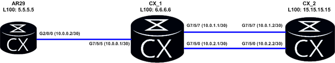
To explain encapsulation process in bit detail, I have created a small topology shown as below in diagram.


As discussed above, depending on the transmission media (In this example transmission media is Ethernet) MAC address in layer 2 headers will keep changing on hop by hop basis.

To generate some traffic, Lets ping from R3 to R2 interface address.As soon as R1 receives the packet from R3, It will remove the L2 information sent by R3 and check the L3 information that is source (20.1.1.2) and destination address (10.1.1.1) available on packet. Then it will look into its routing table to find out going interface i.e. fa0/0 in above example. Once router identify outgoing interface it will attach L2 header before putting the packet on the wire. So now R1 will attach its own interface Mac address as source and R2’s as destination mac address.

Address resolution protocol (ARP) table on R1:


To get closer packet level overview, I have also attached some packet capture taken on R1's interfaces.

Packet capture on R1’s Fa0/1:


Packet capture on R1’s Fa0/0:


Multipoint Broadcast Interfaces, Routing, and ARP


When the router needs to route a packet which matches an entry in the routing table with a next-hop value, it performs Layer 3 to Layer 2 resolution for the next-hop address. If it matches an entry in the routing table with just the outgoing/exit local interface, without a next-hop value, it performs Layer 3 to Layer 2 resolution for the final destination of the IP packet.

From a design perspective, the ideal solution for this problem is to never configure a static route to point out a multipoint interface. Static routes should either point to the next-hop value of the neighbor on the multipoint interface or point to an interface only if it is point-to-point, such as a GRE tunnel, PPP or HDLC link.


When you configure a static route to use an interface attached to a broadcast media (e.g. ethernet), a Cisco router expects that the network is directly attached. As a result it has to ARP for anything that falls within the scope of your static route. Consider the following topology:


Chesterton# ip route 1.2.3.4 255.255.255.255 eth0/0


In this configuration, router Chesterton has to make an ARP request for 1.2.3.4/32 and broadcast it via Ethernet0/0. He is now totally reliant on one of two possiblities:

1.    A Static ARP entry

2.    Vegas will “proxy-arp” his request


If neither of these conditions exists, he won’t be able to reach his destination. The topology presented is a minor case, and as a result there’s no real problem with it. If we were to increase the load, we begin to see a greater set of problems.


Chesterton# no ip route 1.2.3.4 255.255.255.255 eth0/0

Chesterton# ip route 0.0.0.0 0.0.0.0 eth0/0


Now that we’ve added a little more scope for router “Chesterton” to look for, we have a higher possibility for impact. If he attempts to reach 8.8.8.8, 180.0.123.12, and 5.4.3.2 we will see arp entries for each address (all of which will have the MAC address of router Vegas’ e0/0 interface). If there is a lot of traffic from Chesterton to the internet, we have the potential to fill up the arp-cache; thus, causing memory problems that will lead to forwarding problems.

Bottom Line (TL;DR version):


Yes, you can do it and it shouldn’t be a big deal on a small deployment; However, it’s bad practice and could really backfire in a big network.


When configuring a static route, the following options are available:


1-specify only the next-hop value; route is valid as long as a route exists for the next-hop value.

2-Specify only the local outgoing interface; route is valid as long as the interface is in the UP/UP state.
3-Specify both next-hop value and local outgoing interface.


When the third option is selected, the local outgoing interface behaves like a condition for the next-hop value and should be read like: this static route is valid only if the configured next-hop value is reachable over the configured interface, which means as long as the interface is in the UP/UP state and has nothing to do with IP/ARP/NHRP functionality with the next-hop.