An ARP (AddressResolutionProtocol) is a communication protocol that works on a “Physical (Data-Link)” layer of a TCP/IP stack and is used to discover a MAC address of a device on a LAN (local-area network) based on its IP address.
An ARP table is used to store the discovered pairs of the MAC and IP addresses.
In this note i will show how to display the ARP table and how to clear the ARP cache using the Windows arp command.
Windows ARP Command
Show ARP Table
To display the current ARP table in Windows, use the arp command with the -a option:
C:\> arp -a

Interface: 192.168.1.31 --- 0x7
  Internet Address    Physical Address     Type
  192.168.1.1         60-35-c0-6b-a2-b7    dynamic
  192.168.1.255       ff-ff-ff-ff-ff-ff    static
  224.0.0.22          01-00-5e-00-00-16    static
  224.0.0.252         01-00-5e-00-00-fc    static
Show the ARP table in a verbose mode:
C:\> arp -av
To record an IP and MAC address of a device on a LAN to the ARP table, simply ping it:
C:\> ping 192.168.1.95

Pinging 192.168.1.95 with 32 bytes of data:
Reply from 192.168.1.952: bytes=32 time=18ms TTL=64

C:\> arp -a

Interface: 192.168.1.31 --- 0x7
  Internet Address    Physical Address     Type
  192.168.1.1         60-35-c0-6b-a2-b7    dynamic
  192.168.1.95        d6-58-01-33-dd-bc    dynamic
  192.168.1.255       ff-ff-ff-ff-ff-ff    static
  224.0.0.22          01-00-5e-00-00-16    static
  224.0.0.252         01-00-5e-00-00-fc    static
To discover all the devices on a LAN, you can ping them all using this one-liner (adjust the IP of your network):
C:\> FOR /L %i IN (1,1,254) DO ping -n 1 -w 100 192.168.1.%i | FIND /i "Reply"
Clear ARP Cache
To clear an ARP cache it is required to open an elevated command prompt, otherwise you may receive an error as follows: “The ARP entry deletion failed: The requested operation requires elevation.”
To start the elevated command prompt, press the ⊞ Win keybutton to open the start menu, type in cmd to search for the command prompt and press the Ctrl + Shift + Enter to start the command prompt as an administrator.
To clear the ARP cache in Windows, use the arp command with the -d option:
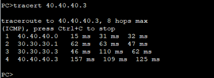
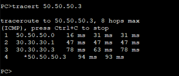
Step 1: As we verified the connectivity between PCs and the path taken by the traffic from PC2 to PC4 and PC3 to PC5.
Traffic from PC2 to PC4 passes through R4Traffic from PC3 to PC5 also passes through R4.
The objective of this lab is to use Policy based routing to ensure traffic from PC2 to PC4 passes through R4 while traffic from PC3 to PC5 passes through R5.
Step 2: Configure ACLs to match traffic from PC2 and PC3 as follows on R3. We use extended ACLs to be able to match the source IP addresses.
***************************R3
#
acl number 3000
 rule 5 permit ip source 40.40.40.0 0.0.0.1
#
acl number 3002
 rule 5 permit ip source 50.50.50.0 0.0.0.1
#
Step 3: Configure PBR and apply it on the interfaces facing PCs on R3.
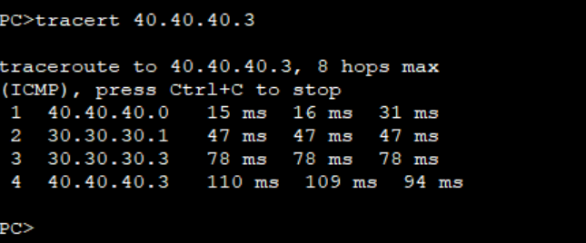
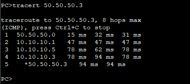
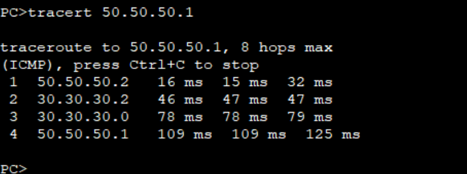
Step 4: Verify the path taken by traffic from PC2 and PC3.
Traffic from PC3 now follows the path through R5 and R7.
Note: The PBR configured on R3 doe not affect the path for the return traffic from PC4 and PC5. You must configure same PBR on R6 to be able to control the flow of the return traffic.
Return traffic from PC5 still goes through R4.
This is how you can use PBR to control traffic flow in your network. Thank You for reading and please leave your comments below. Check out other related articles on our page.
Packet routing is generally carried out by equipment by consulting its routing table where they look for the best routes based on their destination address.
However, what I intend to show is that there are other forms of packet routing, such as PBR, which allows routes to be changed based on other criteria such as source addresses, packet size or next hop.
To show one of the ways to configure packet forwarding based on PBR, I will use an example:
In the company we have two departments that have different access to the Internet due to the needs of the IT Team who need better access to the Internet. What we are going to show is a way to configure the routing of each network for its Internet access, and both teams access the DMZ and can also communicate with each other.
The first step will be to carefully configure an ACL to select only the traffic we want to redirect. As we want to redirect all traffic destined for the Internet, we make the following configuration:
ACL name IT_TEAM number 3001
rule 10 permit ip source 192.168.0.0 0.0.0.255 destination any
rule 15 permit ip source 192.168.1.0 0.0.0.255 destination any
#
ACL Name COM_TEAM number 3002
rule 10 permit ip source 192.168.2.0 0.0.0.255 destination any
rule 15 permit ip source 192.168.3.0 0.0.0.255 destination any
After defining the ACLs, they configured the traffic classifiers
traffic classifier TC_IT_TEAM type or
if-match acl 3001
#
traffic classifier TC_COM_TEAM type or
if-match acl 3002
The next step was to choose what to do with the traffic they had just categorized.
traffic behavior TB_IT_TEAM
redirect nexthop 192.168.0.147
#
traffic behavior TB_COM_TEAM
redirect nexthop 192.168.0.149
As you know after the classifier and traffic behavior are configured they need to be put together to make sense. And that's what they did too.
traffic policy TP_IT_TEAM
classifier TC_IT_TEAM behavior TB_IT_TEAM
#
traffic policy TP_COM_TEAM
classifier TC_COM_TEAM behavior TB_COM_TEAM
Finally, the traffic policies were configured. The only thing left to do was to apply the traffic policies on the switch.
traffic-policy TP_IT_TEAM global inbound
#
traffic-policy TP_COM_TEAM global inbound
After that, traffic destined for the internet was redirected according to the policy.
This is one of the most important because sometimes when we do copy the IOS from flash to TFTP it does not work .
When i was trying to copy , I was getting this error.
switch#copy flash tftp: Source filename flash:c2960s-universalk9-mz.122-55.SE7.bin/cc2960s-universalk9-mz.122-55.SE7.bin Address or name of remote host []? 172.16.10.2 Destination filename [c2960s-universalk9-mz.122-55.SE7.bin]? %Error opening flash:c2960s-universalk9-mz.122-55.SE7.bin/c2960s-universalk9-mz.122-55.SE7.bin (No such file or directory)
To solve the issue , you have to find the correct path by using the command called show version.
Switch#show version Cisco IOS Software, C2960S Software (C2960S-UNIVERSALK9-M), Version 12.2(55)SE7, RELEASE SOFTWARE (fc1) Technical Support: http://www.cisco.com/techsupport Copyright (c) 1986-2013 by Cisco Systems, Inc. Compiled Mon 28-Jan-13 10:28 by prod_rel_team Image text-base: 0x00003000, data-base: 0x01B00000 ROM: Bootstrap program is Alpha board boot loader BOOTLDR: C2960S Boot Loader (C2960S-HBOOT-M) Version 12.2(55r)SE, RELEASE SOFTWARE (fc1) GOODWILL-POP uptime is 4 hours, 15 minutes System returned to ROM by power-on System image file is "flash:/c2960s-universalk9-mz.122-55.SE7/c2960s-universalk9-mz.122-55.SE7.bin"
Switch#copy flash tftp: Source filename [c2960s-universalk9-mz.122-55.SE7]? flash:/c2960s-universalk9-mz.122-55.SE7/c2960s-universalk9-mz.122-55.SE7.bin Address or name of remote host []? 172.16.10.2 Destination filename [c2960s-universalk9-mz.122-55.SE7.bin]? !!!!!!!!!!!!!!!!!!!!!!!!!!!!!!!!!!!!!!!!!!!! 10979547 bytes copied in 36.936 secs (297259 bytes/sec) Switch#
To upgrade the IOS you need to have a tftp server connected to your switch and there must be a layer-3 reachability between TFTP server and the Switch.
I am assuming you have configured the TFTP server properly and make sure, in your TFTP server The firewall and antivirus is disabled.
Step-1=Copy the IOS file from TFTP to your server.
SW1#show spanning-tree bridge detail
VLAN0001
  Bridge ID  Priority    32769  (priority 32768 sys-id-ext 1)
             Address     5254.001a.935a
             Hello Time   2 sec  Max Age 20 sec  Forward Delay 15 sec
VLAN0010
  Bridge ID  Priority    32778  (priority 32768 sys-id-ext 10)
             Address     5254.001a.935a
             Hello Time   2 sec  Max Age 20 sec  Forward Delay 15 sec
VLAN0020
  Bridge ID  Priority    32788  (priority 32768 sys-id-ext 20)
             Address     5254.001a.935a
             Hello Time   2 sec  Max Age 20 sec  Forward Delay 15 sec
VLAN0030
  Bridge ID  Priority    32798  (priority 32768 sys-id-ext 30)
             Address     5254.001a.935a
             Hello Time   2 sec  Max Age 20 sec  Forward Delay 15 sec
SW2#show spanning-tree bridge detail
VLAN0001
  Bridge ID  Priority    32769  (priority 32768 sys-id-ext 1)
             Address     5254.0015.bc74
             Hello Time   2 sec  Max Age 20 sec  Forward Delay 15 sec
VLAN0010
  Bridge ID  Priority    32778  (priority 32768 sys-id-ext 10)
             Address     5254.0015.bc74
             Hello Time   2 sec  Max Age 20 sec  Forward Delay 15 sec
VLAN0020
  Bridge ID  Priority    32788  (priority 32768 sys-id-ext 20)
             Address     5254.0015.bc74
             Hello Time   2 sec  Max Age 20 sec  Forward Delay 15 sec
VLAN0030
  Bridge ID  Priority    32798  (priority 32768 sys-id-ext 30)
             Address     5254.0015.bc74
             Hello Time   2 sec  Max Age 20 sec  Forward Delay 15 sec
SW3#show spanning-tree bridge detail
VLAN0001
  Bridge ID  Priority    32769  (priority 32768 sys-id-ext 1)
             Address     5254.001d.e6bb
             Hello Time   2 sec  Max Age 20 sec  Forward Delay 15 sec
VLAN0010
  Bridge ID  Priority    32778  (priority 32768 sys-id-ext 10)
             Address     5254.001d.e6bb
             Hello Time   2 sec  Max Age 20 sec  Forward Delay 15 sec
VLAN0020
  Bridge ID  Priority    32788  (priority 32768 sys-id-ext 20)
             Address     5254.001d.e6bb
             Hello Time   2 sec  Max Age 20 sec  Forward Delay 15 sec
VLAN0030
  Bridge ID  Priority    32798  (priority 32768 sys-id-ext 30)
             Address     5254.001d.e6bb
             Hello Time   2 sec  Max Age 20 sec  Forward Delay 15 sec
The priority has a default value of 32768 so without configuring anything, the MAC address is the tie-breaker. In my case, SW2 is the root bridge for all VLANs:
SW2#show spanning-tree vlan 10

VLAN0010
  Spanning tree enabled protocol ieee
  Root ID    Priority    32778
             Address     5254.0015.bc74
             This bridge is the root
             Hello Time   2 sec  Max Age 20 sec  Forward Delay 15 sec

  Bridge ID  Priority    32778  (priority 32768 sys-id-ext 10)
             Address     5254.0015.bc74
             Hello Time   2 sec  Max Age 20 sec  Forward Delay 15 sec
             Aging Time  15  sec

Interface           Role Sts Cost      Prio.Nbr Type
------------------- ---- --- --------- -------- --------------------------------
Gi0/0               Desg FWD 4         128.1    P2p
Gi0/1               Desg FWD 4         128.2    P2p
SW2#show spanning-tree vlan 20

VLAN0020
  Spanning tree enabled protocol ieee
  Root ID    Priority    32788
             Address     5254.0015.bc74
             This bridge is the root
             Hello Time   2 sec  Max Age 20 sec  Forward Delay 15 sec

  Bridge ID  Priority    32788  (priority 32768 sys-id-ext 20)
             Address     5254.0015.bc74
             Hello Time   2 sec  Max Age 20 sec  Forward Delay 15 sec
             Aging Time  300 sec

Interface           Role Sts Cost      Prio.Nbr Type
------------------- ---- --- --------- -------- --------------------------------
Gi0/0               Desg FWD 4         128.1    P2p
Gi0/1               Desg FWD 4         128.2    P2p
SW2#show spanning-tree vlan 30

VLAN0030
  Spanning tree enabled protocol ieee
  Root ID    Priority    32798
             Address     5254.0015.bc74
             This bridge is the root
             Hello Time   2 sec  Max Age 20 sec  Forward Delay 15 sec

  Bridge ID  Priority    32798  (priority 32768 sys-id-ext 30)
             Address     5254.0015.bc74
             Hello Time   2 sec  Max Age 20 sec  Forward Delay 15 sec
             Aging Time  300 sec

Interface           Role Sts Cost      Prio.Nbr Type
------------------- ---- --- --------- -------- --------------------------------
Gi0/0               Desg FWD 4         128.1    P2p
Gi0/1               Desg FWD 4         128.2    P2p
Let’s see what we can do about that. I want to configure my network so it looks like this:
spanning-tree Configuration
We can change the root bridge for each VLAN with the spanning-tree Command. Here are our options:
SW1(config)#spanning-tree vlan 10 ?
  forward-time  Set the forward delay for the spanning tree
  hello-time    Set the hello interval for the spanning tree
  max-age       Set the max age interval for the spanning tree
  priority      Set the bridge priority for the spanning tree
  root          Configure switch as root
Above, we see two options:
priority: We can manually change the bridge priority.
root: We can configure the switch as root.
What’s the difference between these two parameters? Let’s find out.
The spanning-tree vlan command also accepts ranges of VLANs.
Root Parameter
We’ll start with the root parameter. Let’s check our options:
SW1(config)#spanning-tree vlan 10 root ?
  primary    Configure this switch as primary root for this spanning tree
  secondary  Configure switch as secondary root
I can configure the switch to become the primary or secondary root bridge. Let’s try primary:
SW1(config)#spanning-tree vlan 10 root primary
Let’s check whether that works:
SW1#show spanning-tree vlan 10

VLAN0010
  Spanning tree enabled protocol ieee
  Root ID    Priority    24586
             Address     5254.001a.935a
             This bridge is the root
             Hello Time   2 sec  Max Age 20 sec  Forward Delay 15 sec

  Bridge ID  Priority    24586  (priority 24576 sys-id-ext 10)
             Address     5254.001a.935a
             Hello Time   2 sec  Max Age 20 sec  Forward Delay 15 sec
             Aging Time  15  sec

Interface           Role Sts Cost      Prio.Nbr Type
------------------- ---- --- --------- -------- --------------------------------
Gi0/0               Desg FWD 4         128.1    P2p
Gi0/1               Desg FWD 4         128.2    P2p
In the output above, we see that SW1 is now the root bridge for VLAN 10. The priority of SW1 is now 24586.
We can also configure another switch to become the “secondary” root bridge. Let’s try that on SW2:
SW2(config)#spanning-tree vlan 10 root secondary
Let’s check what this command does:
SW2#show spanning-tree vlan 10

VLAN0010
  Spanning tree enabled protocol ieee
  Root ID    Priority    24586
             Address     5254.001a.935a
             Cost        4
             Port        1 (GigabitEthernet0/0)
             Hello Time   2 sec  Max Age 20 sec  Forward Delay 15 sec

  Bridge ID  Priority    28682  (priority 28672 sys-id-ext 10)
             Address     5254.0015.bc74
             Hello Time   2 sec  Max Age 20 sec  Forward Delay 15 sec
             Aging Time  300 sec

Interface           Role Sts Cost      Prio.Nbr Type
------------------- ---- --- --------- -------- --------------------------------
Gi0/0               Root FWD 4         128.1    P2p
Gi0/1               Desg FWD 4         128.2    P2p
Above, we see that the priority of SW2 is now 28682. In reality, there is no such thing as a “secondary” root bridge.
What happens is that behind the scenes,Cisco IOS sets a prioritywhen you use the root primary or root secondary parameters. We can verify this by looking at our configuration:
SW1#show running-config | include priority
spanning-tree vlan 10 priority 24576
SW2#show running-config | include priority
spanning-tree vlan 10 priority 28672
The way this works is that the switch looks at the priority of the current root bridge and then decreases its own priority so that it becomes the new root bridge.
Priority Parameter
We can also configure the priority manually like this:
SW2(config)#spanning-tree vlan 20 priority ?
  <0-61440>  bridge priority in increments of 4096
Let’s try that on SW2 for VLAN 20:
SW2(config)#spanning-tree vlan 20 priority 0
By setting the priority to 0, I’ll have the lowest possible priority. Let’s check whether SW2 is now the root bridge for VLAN 20:
SW2#show spanning-tree vlan 20

VLAN0020
  Spanning tree enabled protocol ieee
  Root ID    Priority    20
             Address     5254.0015.bc74
             This bridge is the root
             Hello Time   2 sec  Max Age 20 sec  Forward Delay 15 sec

  Bridge ID  Priority    20     (priority 0 sys-id-ext 20)
             Address     5254.0015.bc74
             Hello Time   2 sec  Max Age 20 sec  Forward Delay 15 sec
             Aging Time  300 sec

Interface           Role Sts Cost      Prio.Nbr Type
------------------- ---- --- --------- -------- --------------------------------
Gi0/0               Desg FWD 4         128.1    P2p
Gi0/1               Desg FWD 4         128.2    P2p
Above, we see that the priority is now 20 (priority 0 and sys-id-ext 20). Let’s configure SW3 to become the root bridge for VLAN 30:
SW3(config)#spanning-tree vlan 30 priority 0
Here’s the output of SW3:
SW3#show spanning-tree vlan 30

VLAN0030
  Spanning tree enabled protocol ieee
  Root ID    Priority    30
             Address     5254.001d.e6bb
             This bridge is the root
             Hello Time   2 sec  Max Age 20 sec  Forward Delay 15 sec

  Bridge ID  Priority    30     (priority 0 sys-id-ext 30)
             Address     5254.001d.e6bb
             Hello Time   2 sec  Max Age 20 sec  Forward Delay 15 sec
             Aging Time  300 sec

Interface           Role Sts Cost      Prio.Nbr Type
------------------- ---- --- --------- -------- --------------------------------
Gi0/0               Desg FWD 4         128.1    P2p
Gi0/1               Desg FWD 4         128.2    P2p
And as we can see above, SW3 is the root bridge for VLAN 30. That’s all there is to it.
Conclusion
You have now learned how to:
Verify the current root bridge per VLAN.
Configure the root bridge using the spanning-tree command:Using the root parameter.Using the priority parameter.